The New York Municipal Car (BMT Standards) (1915-1921)

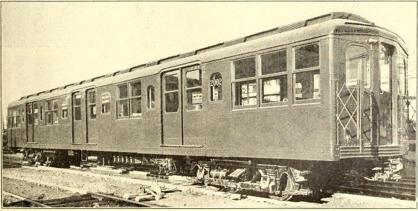
New York Municipal Car -- The First Eight-Car Train Ready For A Trial Run On The New Sea Beach Line.
Design
Electric Railway Journal · Vol. 43, No. 23 · June 6, 1914 · pp 1261-1267.
The Present Article Tells Why the New York Municipal Railway Corporation Devised and Adopted a Car of Great Length and Unusual Width for Its Rapid Transit Train Service—Comparisons with Earlier Car Types of Different Railways Show Wherein the New Car Is Superior— One Hundred Cars Are Now on Order, with 500 More Under Option.
When the Brooklyn Rapid Transit System offered on March 2, 1911, to operate a part of the vast subway and elevated network then projected by the city of New York, its engineering and operating forces had to face the question of finding a car that would meet the probable service conditions in the most satisfactory way. If the new lines were to be mere fractional additions to existing structures, the answer would have been the very simple one of duplicating the last preceding types of the Brooklyn system. But since the contract made by the Brooklyn Rapid Transit System through the allied New York Municipal Railway Corporation covered 225 miles of elevated line (including fills and cuts) and 68.6 miles of subway, measured as single track, the conditions were absolutely reversed because the new routes alone will be, when complete, nearly twice the present 105 miles of the Brooklyn elevated routes and their surface extensions. Hence the logical thing was to develop a car best suited for the new lines and to alter the old lines to conform to the standard set by the new.
Capacity the Basic Object

N. Y. M. Car—Side Elevation and Plan, Showing Three Sets of Double Doors and Combinations of Transverse with Fixed and Folding Longitudinal Seats.
From the moment that the first rough sketches were made for the new car, the prime object was to secure the greatest possible capacity from structure and unit car alike. Studies which had previously been carried out by the Brooklyn Rapid Transit System for surface railways indicated that the all-steel side-entrance car was the most efficient in passenger-carrying capacity. The same principle of design applied to non-surface cars, but with the addition that clearance conditions were usually far more liberal in subway-elevated work than on surface railways. This spatial freedom suggested the possibility of using a car much wider and longer than the ordinary standards.
Aside from any other advantages, the successful development of the wide-car idea means in round but staggering numbers, that a $200,000,000 structure with cars 67 ft. long x 10 ft. wide will carry eventually as many passengers as a $240,000,000 structure with cars 52 ft. 3/4 in. long x 8 ft. 6 3/4 in. wide, the latter dimensions being those of the cars used in the present subway in New York. The possibility for this enormous saving in structural costs alone may be illustrated by the calculation that in one hour 400 of the present B. R. T. cars, with an average load of 152 passengers per car, would carry only 60,800 passengers past a given point of single track, whereas the same train length (18,863.5 ft.) comprising 280.5 N. Y. M. cars, with a load of 270 passengers per car, would carry 75,735 passengers by the same point—an increase of about 25 per cent in track capacity. Compared with the Interborough car, the increase in track capacity is 21 per cent.
Clearance Studies and Structural Changes
Before taking up the design of the car in detail it was, of course, essential to make clearance studies of every foot of route over which the proposed car would be likely to run. To be sure, the city of New York had committed itself to a subway profile and an elevated railway clearance which would permit cars of approximately 10 ft. width, but such a dimension had not been contemplated either in the design of the city's existing East River bridges or in the erection of the railway's elevated structures and platforms. The result of the clearance study showed that out of a possible total of 398.35 miles of track, only 57.31 miles could not be operated with the longer and wider cars unless certain changes were made on the bridges and existing elevated lines. Fortunately, these alterations, as a whole, were not prohibitive: First, because the city had already decided to build wide profile tunnels and subways; second, the cost of the new elevated structures would not be affected by the width of car in any event; third, the Brooklyn Rapid Transit System had been rebuilding or reinforcing its elevated structures for some years past, and still more radical changes, like third-tracking, were required in connection with the new rapid transit routes. Thus the expense of adapting the way would be very reasonable in comparison with the advantages of the proposed car.
One other structural condition had to be met, namely, that of concentrated wheel loads. The Brooklyn elevated lines had been reinforced, beginning in the year 1904, for a maximum wheel load of 10,500 lb. In the succeeding year the wheel load on some cars had risen to 12,900 lb. As time went on the structures had to be reinforced for loads of 14,000 lb. per wheel, as imposed by the company's own rolling stock. A still higher load, 15,000 lb., is imposed during the summer months on certain routes by the Rockaway Beach through cars of the Long Island Railroad. Since 15,000 lb. per wheel, or 30,000 lb. per axle, is also the limit set by the city of New York for its own structures, it was necessary that the loads per wheel of the new car should approximate this figure. Here the problem was solved by a better distribution of weight throughout the car, including the use of eccentrically-loaded trucks. Roughly speaking, the 1400 series B. R. T. elevated car, with its two 200-hp motors on one truck, has a maximum load of 13,500 lb. per wheel; the longer and wider N. Y. M. car with but one 140-hp motor per truck imposes a corresponding load per wheel of 14,950 lb. At the assumed total weight of 122,800 lb. (85,000-lb. car plus 270 passengers at 140 lb. each), the weight per wheel will be 627 lb. (15,577 lb.-14,950 lb.) less than that of a driving wheel on the much smaller Interborough motor car owing to the fact that the two 200-hp motors of the latter car are on one truck. Since every car is a motor car, it was found possible to provide for a higher percentage of weight on drivers than is usual in trailer operation. The rate of acceleration will be 1.25 m.p.h.p.s.

N. Y. M. Car—Relation of Old Rapid Transit Lines of Brooklyn Rapid Transit System to the Additional Lines. All to Be Operated by the New York Municipal Railway Corporation.
Studies of Previous Designs
Before deciding on a standard car, the New York Municipal Railway Corporation made a most painstaking study of the constructional, seating and cost features of existing electric rapid transit cars. This study extended even to the seating plans of the suburban cars of European steam railroads. However, one important point which was realized in reviewing the rolling stock of steam or electrified suburban lines was that the operators of such service must perforce give a higher ratio of seating to passenger capacity than operators of short-run city high-speed lines. The suburban passenger pays a fare reasonably proportionate to the distance traveled, and he usually rides an hour or more. Furthermore, as the headway of steam or electrified suburban lines is rarely less than ten minutes, there is generally no reason why a seat cannot be supplied to every passenger at all times.
The seat-use conditions on city rapid transit lines are fundamentally different. The passenger pays a single 5-cent fare for practically any distance he chooses to ride. Although in point of time the average trip may last only half an hour, an equivalent ride on the steam suburban lines would cost two to four times as much. But still more important is the fact that under such conditions as obtain in New York's present subway, it is physically impossible to seat all rush-hour passengers throughout the trip, despite the operation of the maximum train length (ten cars totaling 520 ft. 7 1/2 in.) and the shortest possible headway, ninety seconds. Since, therefore, a city rapid transit line cannot emulate steam suburban roads in supplying seats to all rush-hour passengers, the designers of the present car evolved an arrangement which in providing the maximum standing and seating room for the heavy and light hours respectively would give a most logical and flexible means of handling the variations of city traffic.
To appreciate this real innovation in floor use it will be necessary to look backward over the changes made in the original subway cars of the Interborough Rapid Transit Company. As first built these cars had longitudinal seating except at the center which was provided with pairs of the orthodox back-to-back transverse seats. Although these cars were but 52 ft. 0 3/4 in. over all, it soon became apparent that end-door passage was insufficient to permit short station stops. Beginning in 1910, after six years of operation, the transverse seats on each side were removed to make way for a center door of 4 ft. 2 in. opening. The efficiency of the vestibule doorways, which were also of this width, was improved by the practical removal of bulkheads. Thus the Interborough car of to-day has none but longitudinal seating, and the loss of the cross seats has been compensated only in small part by the use of hinged seats which are lowered alongside of idle center doors in line with the other seating. The total passage space per side of these rebuilt cars amounts to 24 per cent of the total length. The conditions of door operation, however, do not permit all openings to be used to the best advantage. The guard must stand with one foot on each platform of adjacent cars as he opens the heavy vestibule doors by hand, and he is therefore in a position unfavorable for controlling the movement of passengers at the air-operated center door. With this knowledge of the Interborough Company's experiences, it will be easier to appreciate the radically different plan which the New York Municipal Railway Corporation has devised for the same public and for much the same speeds and schedules.
The fundamental principle of the N. Y. M. design is to attain maximum seating capacity during hours of normal traffic and maximum standing room plus a reasonable proportion of seating capacity during the rush hours. As the accompanying plan indicates, this has been attained by the use of folding seats just as in the revised Interborough car, but on a wider scale because of the greater number of doors. Furthermore, a great part of the seats are of the more comfortable transverse type. As shown on the plans dated July 15, 1911, the original intention of the New York Municipal Railway Corporation was to use only the center doors during the hours of light traffic, thereby making available for folding seats the space alongside of the end-side doors. Owing to the length of the car it was decided eventually to use during light hours one of the two 32 in. doors forming each pair of side doors. Consequently, the average walk of the passenger during normal hours will not be much different from that during the rush hours.
How More Capacity Was Obtained
In working out a plan for maximum capacity, the company took a leaf from the book of electrified steam railroad practice in determining to use the widest and longest car possible. The constructional feasibility of such cars was unquestionable, for the Southern Pacific Railroad was using 72-ft. x 10-ft. 6-in. cars on its Oakland (Cal.) suburban lines, while the Long Island Railroad was operating into Brooklyn cars of 65-ft. x 9-ft. 11 1/2-in. body. The point in which the N. Y. M. car differs from these and other designs lies in the better exploitation of the width, due partly to lesser wall thickness but chiefly to seating layout. In the usual suburban cars all but the corner seats are transverse. Each seat cares for two passengers but with several inches to spare, and the aisle is also wider than necessary. In the Brooklyn car, the clear inside width of 9 ft. 1 5/8 in. is enough to permit the placing of a triple cross-seat opposite every double cross-seat. As the seating plan shows, the triple seat has 52 1/2-in. clearance for seating while the double seat has 34 in. This space of at least 17 in. per passenger is actually 1 1/2 in. greater than the double cushions of some surface cars. The aisle between the transverse seats is only 21 1/8 in. wide but it will be observed that it is hardly an aisle in the usual sense of the word. This arrangement will be referred to later.

N. Y. M. Car-Analysis of Door Location Relative to Passenger Movement.

N. Y. M. Car—Comparisons of Door and Seating Layouts of Leading Types of City Rapid Transit Cars Which Were Studied to Work Out the Equal Use of All Side Doors of the New York Municipal Car. (See Table Above in Connection with Division of Cars Into Sections).

N. Y. M. Car—Comparisons of Side Elevations of the Standard Cars of the Interborough Rapid Transit Company and of the New York Municipal Railway Corporation to Show Differences in Length and Depth.
The second means adopted to secure greater seating capacity per car was to use three pairs of side doors and thus eliminate vestibules. These doors take up 24 per cent of the car length, which is practically that of the present Interborough cars. Their efficiency for passenger movement should be greater, however, because the guard will stand in the center of the car. Further, he will operate all doors pneumatically, so that his attention will not be distracted by the manipulation of heavy door levers. The maximum distance from the guard's position to the end side-doors is about 17 ft. Had end instead of side doors been used on a car of this length, the time of passenger interchange would have been prohibitive.
The use of side doors made it possible to divide the car into sections of such capacity that each doorway will do its fair share of work. As the result of this analysis of door location, the average walk of a passenger during the rush hours will be 83.6 in. compared with 90.5 in. on the Interborough center-door car, 91.6 in. on the Cambridge subway side-door car of the Boston Elevated Railway, 87 in. on the Hudson & Manhattan center-door car, and 146 in. on the B. R. T. end-door elevated car. These figures indicate clearly the superiority of side doors as compared with end doors alone, or with end doors plus center doors. The Cambridge car, which also has three doorways per side, is naturally the nearest to the new N. Y. M. design, and the difference against the Cambridge car is due chiefly to its greater length. The method of obtaining this comparison of passenger movement is shown in an accompanying series of plans with its table of passenger capacities accord ing to car sections and the simple formula of "nd/N = D" where N equals total seated and standing load, n equals number of passengers in each section indicated on plans, d equals average distance of each section to door in inches, and D equals average distance to doors per passenger in inches.
The seating, standing and door layout complete of the new car is intended to meet the essential condition of short station stops on a line with headways as short as 90 seconds. The space opposite each active doorway is free except for vertical stanchions to accommodate standing passengers and for a 34 1/16-in. seat alongside one-half of the opposite doorway. Contiguous to this section are facing pairs of 4-ft. 4 1/2-in. longitudinal seats with a 5-ft. 6 3/8-in. space between. The triple and double back-to-back cross-seats follow. At the ends of the car, transverse and short side seats are arranged to the best advantage. When not in use the motorman's seat is folded against the wainscoting at the window sill, thereby permitting a two-passenger rattan seat to be drawn forth from beneath an adjoining seat.
In general, the plan of grouping standing passengers on wide square areas is considered more effective than to have them crowd into a long narrow aisle. While end doors are provided, it is expected that the better distribution of the load due to the use of entrances at each end of the station platform and to automatically operated side doors at three points per car length will minimize "bunching" of passengers on station platforms and their later pushing through a car or cars for a seat.
Comparisons of Seating Capacity
The foregoing paragraphs have explained the reasons for adopting a wide, long car with a combination of transverse seats, short longitudinal seats and standing areas for rectangular groups rather than for narrow files of passengers. It is now in order to see what this plan means in actual figures when compared with the car and train capacities of other city and suburban rapid transit companies. The basic figures will be found in the accompanying table of comparative data.
The first point to be noted in this table is that the Interborough and the N. Y. M. cars are the only ones which have some temporary seating. The variation of the Interborough center-door car from minimum to maximum is forty-four to forty-eight seats, while that of the N. Y. M. side-door car is from seventy-eight to ninety. Even under the conditions of minimum seating, the N. Y. M. car will seat 28.8 per cent and the Interborough car 26 per cent of the passengers. In these and any other comparisons for this side-door car, standing capacity is figured on the basis of 9 in. knee room for passengers in the longitudinal seats and a free area of 1 1/2 sq. ft. per standing passenger.
Generally speaking, both the seating and standing capacity of the new car exceed that of all the other cars shown in the table. It is particularly interesting to make a comparison with the Interborough car because the latter design is the one which would naturally be studied most carefully by a neighboring railway. Car for car this comparison will show that in maximum seating and standing capacity the new car exceeds the Interborough by about 60 per cent on the basis of greatest load. The influence of greater width and difference in seating appears by a comparison of the total seated and standing load per running foot of car which gives a figure of 4.0 passengers for the N. Y. M., 3.25 for the Interborough and 3.12 for the B. R. T. elevated car.
A comparison of the cars in the New York metropolitan district was also worked out on the basis of areas as follows: New York Municipal car, 67 ft. long, equals net area 590 sq. ft. Long Island car, 64 ft. long, equals net area 544 sq. ft. Interborough car, 52 ft. 0% in. long equals net area 373 sq. ft. Hudson & Manhattan car, 48 ft. 4 in. long, equals net area 362 sq. ft.
Thus the area of the New York Municipal car is 8.5 per cent greater than the new Long Island car, 58 per cent more than the Interborough car and 63 per cent more than the Hudson & Manhattan car. It should be understood that the areas given are net, namely, they include only the space bounded by the inside dimensions of the car. Taking the maximum seating arrangement of each, the following areas per seated passenger result: Long Island, 7.6 sq. ft.; Interborough, 7.8 sq. ft.; Hudson & Manhattan, 8 sq. ft.; New York Municipal Railway, 6.5 sq. ft.

N. Y. M. Car—Seat and Door Use Studies Recorded under Date of July 15, 1911, Showing that the Original Idea Was to Permit Separate Full-Width Entrance and Exit in Rush Hours, Half-Width of the Same Passages for Medium Hours and One Central Passage for Light Hours.
Platform Savings of Long Wide Car
It has been stated previously that the gain in track capacity due to adopting the new car would readily outweigh the cost of any structural changes. An enormous saving in platform expense also will follow from using a wide car of great length and with side-door passages exclusively. The following comparison made with the present B. R. T. elevated cars shows this feature in a most interesting manner:

Platform Costs Per Annum.
From this table it was determined that if 600 of the larger cars were used for the same number of car hours (3071 per car a year), the platform cost would be about $700,000 per annum, or a saving of more than $200,000 per annum.
Another advantage which will accrue to the transportation department from the operation of these cars as motor cars only is the simplification and reduction of yard labor concurrent with far more flexible train combinations than are possible with the use of trailers.
Comparison of Weights and Motor Capacities
As noted in the earlier paragraphs relative to weights on structure, the concentrated loads of the new car will not greatly exceed those of the much shorter elevated cars now in service. The total weight of the N. Y. M. car, of course, is greater, but the advance in design is indicated by the fact that this all-steel sidedoor car weighs 1268 lb. per running foot (light) of motor car compared with 1455 lb. per running foot (light) of the narrower Brooklyn 1400 series elevated motor car with steel underframe but wooden superstructure. The 1268 lb. per running foot of the N. Y. M. all motor-car train is also much less than that of the other end-entrance and center-entrance shown in the table of comparative data. The end-entrance motor cars are highest with a top figure of 1620 lb. Then follow center-entrance cars with a top figure of 1533 lb. The remodeled Interborough all-steel motor car shows 1496 lb. per running foot, while even its lowest train weight of 1292 lb., obtained by averaging three motors and two trailers, is more than the N. Y. M. allmotor-car train. The Cambridge side-door design of the Boston Elevated Railway is apparently the lightest per running foot (1235 lb.) but actually it is slightly heavier when its lesser width is considered.
On the basis of weight when maximum capacity is carried, the N. Y. M. car shows a saving of 83 lb. to 145 lb. per passenger over the Interborough, depending upon comparison with different combinations of motor and trail cars or straight motor cars. In the new car the estimated weight per passenger on the basis of 270 passengers is the astoundingly low figure of 315 lb. but 11 lb. more than the Interborough trailer. Likewise the weights per seated passenger, namely, 1089 lb. and 944 lb. (corresponding to the minimum and maximum seating layouts) are actually below the unit weights of many surface railway low-speed cars. The advance in design and difference in seat arrangement are so great that the new motor car weighs 580 lb. less per seat under minimum and 678 lb. less per seat under maximum seating conditions than the motor car of the Interborough Rapid Transit Company.
Because of the enormous savings in weight and the use of a tap field motor for the varied service conditions, this 67-ft. car will carry only two 140-hp. motors, whereas the Southern Pacific cars have four 125-hp. motors, and the shorter Long Island, Hudson & Manhattan, and Interborough cars two 220-hp., two 225-hp., and two 200-hp. motors respectively. Compared with the Interborough operation, it will be found that the new car's figure of 1.04-hp. per passenger on the basis of maximum loading is much below that of the Interborough. Nevertheless, the N. Y. M. all-motor train will amply meet the speed conditions mentioned in the following paragraph. While the percentage of weight on the drivers is below that of an Interborough motor car (never operated singly in passenger service) it exceeds that of all Interborough train combinations of motor cars and trailers.
Fully loaded trains, according to the specifications of the Public Service Commission, must operate at the required speeds over 3 per cent grades and at reasonable speeds over the 5 per cent grades on the bridge approaches. The motor equipments will permit a schedule speed of 25 m.p.h. for express trains between the terminals of express stations and a schedule speed of 15 m.p.h. for local trains between terminals. The motor specifications provide for a maximum speed of 50 m.p.h.

N. Y. M. Car-Table of Comparative Data for Various Elevated and Subway Cars.
Costs
Through the courtesy of several of the electric railway operators previously mentioned detailed total and unit costs of various types of modern steel passenger cars were obtained. These figures are presented in the accompanying table without any identification except that the last set of figures relate to the estimated cost of the N. Y. M. car. This estimate shows that the estimated cost per passenger seat of the N. Y. M. car ready for service is less than of all other designs, and the cost per passenger capacity seated and standing less than of all others but one. Even the cost per running foot is less than that of the Interborough and Hudson & Manhattan motor cars of lesser width. The parallel would be still more favorable to the N. Y. M. car if it had not been equipped with so many new safety and operating features, all of which naturally add to the cost of the car.
Particularly careful comparisons were made with the latest B. R. T. elevated car and Interborough subway car. It was found that the maximum capacity of 600 N. Y. M. (270-passenger) cars, costing $9,000,000 would call for 1070 Brooklyn Rapid Transit (152-passenger) cars at a cost of $13,414,590. The cost of a standard Interborough train of seven motors and three trailers is $234.33 per running foot, while that of the wider N. Y. M. train of any length will be $223.88 per running foot. Assuming the Interborough train makeup stated, the 600 N. Y. M. cars would cost $1,980,000 less than 900 Interborough cars. The N. Y. M. cars would also carry 162,000 instead of 152,100 passengers.

Comparative Costs - Various Steel Passenger Cars.
Conclusion
The adoption of a car 67 ft. long x 10 ft. wide instead of the smaller type now used by the Interborough Rapid Transit Company on the New York subway system will increase the ultimate carrying capacity of the track by 20 to 25 per cent, save about $200,000 a year in platform costs, save about $2,000,000 on an order for 600 cars and save another $1,000,000 to $2,000,000 in power system capacity because of the decreased energy consumption per passenger carried.
Car Body
Electric Railway Journal · Vol. 43, No. 24 · June 13, 1914 · pp 1327-1333.
The Present Article Is a Detailed Description of the Construction of the Body—Among Noteworthy Features Are the Substantial End Stiffening for a Full Side-Girder Design, the Compromise Roof Design to Provide for Tunnel Clearances While Retaining Ventilation Advantages of the Monitor Deck and Absence of Floors Under Seats to Save Weight.
On Feb. 26, 1914, the New York Municipal Railway Corporation placed with the American Car & Foundry Company an order for the bodies of 100 cars to be used in subway and elevated service. The contract with the car builder calls for the delivery of the complete order by Dec. 1, 1914. In addition, the railway reserves the right to order 500 more cars for delivery within three years from the date of the present agreement. The cars which are now under order are of the 67-ft. x 10-ft. side-door design described in the June 6 issue. The present article will describe such features of the framing and general body construction as correspond fairly closely to the specifications which were accepted by the car builder.
Division of Duties Between Railway and Car Builder
In accordance with the practice of the allied Brooklyn Rapid Transit System, all electrical, mechanical and pneumatic apparatus, etc., will be installed by the New York Municipal Railway Corporation. This equipment comprises the following: Motors, control, air brakes, door-operating mechanism, heaters, signals, lighting fixtures, fire extinguishers and practically all of the wiring. The company has also furnished but left to the car builder for installation f.o.b. Berwick, Pa., the following items: Trucks: draft gears, drawbars and coupler heads with radial bar and gear attachments and carbody center plates.
The car builder will furnish and install the following accessories for the apparatus supplied by the railway: Conduit pipe, fittings, hangers, brackets, etc., for the control, lighting, heating, signaling and auxiliary circuits; hangers, brackets, etc., for the air brakes; foundation brake rigging and hand brakes complete; brackets and attachments for the door-operating devices; draft sills and reinforcements for couplers and draft gears.
In general, the foregoing paragraphs delineate the division of duties between the railway and the car builder. The intent of the railway in having the car builder do so much miscellaneous work is to enjoy the advantage of laying out beforehand all jobs that would, if done subsequently, injure the finish of the car. As matters are now being handled, the cars will reach Brooklyn with the conduit and piping in place; and if the cars are built rapidly enough they will be delivered with the terminals of the different wires hanging out of the conduit for attachment to the lighting fixtures.
Materials
A careful study was made to determine the most desirable material for the different parts of the car body, with the result that an unusual variety of metals was specified. The uses and characteristics of each class of material are summarized in the following paragraphs:
Structural steel shapes: A.S.T.M. specification for "Steel Shapes, Universal Mill Plates and Bars," dated June 1, 1912.
Rivets more than 1/4-in. diameter: A.S.T.M. specification for "Rivet Steel," dated June 1, 1912; rivets of 1/4-in. and less diameter, Norway iron.
Steel castings: Open hearth or crucible steel—phosphorus not to exceed 0.05 per cent; sulphur not to exceed 0.05 per cent; tensile stress per square inch not less than 60,000 lb.; elastic limit per square inch not less than 27,000 lb.; elongation in 2 in. not less than 30 per cent.
Malleable iron castings: A.S.T.M. specification for "Malleable Iron Castings," dated Nov. 15, 1904.
Gray iron castings: A.S.T.M. specification for "Gray Iron Castings," dated Sept. 1, 1905.
Wrought iron: A.S.T.M. specification for "Refined Wrought Iron Bars," dated June 1, 1912.
Bronze hardware composition: Copper, 88.4 per cent; tin, 5.5 per cent; lead, 2.8 per cent; zinc, 3.3 per cent. Impurities exceeding 1.5 per cent are not allowed, but a variation of 10 per cent in the specified amounts of tin, lead and zinc will be permitted.
Perhaps the most interesting feature of the various uses of metal is the adoption of "ingot iron" for floor sheets, doors and roof on account of its rust-resisting qualities. Floor sheets are exposed to the atmosphere, and even galvanized iron will rust at the connections with the rivets. In the case of doors, moisture will penetrate to places which cannot be repainted, which fact is one of the objections to steel doors. Roofs are subject to much moisture, and here the selection of "ingot iron" makes it possible to use thinner sheets than would be practicable with steel.
For rolled steel and ingot iron sheets and plates, the company specified three grades of steel and one grade of "ingot iron" according to the use to which they were to be applied, as follows: Grade A--thin steel for moldings, interior trim, etc. Grade B--flattened steel used for outside and inside finishings, posts, etc. Grade C--all other rolled steel sheets and shapes. Grade D--ingot iron sheets for roofs, floor sheets, ventilators, doors, etc.
The specifications for Grades A, B, C steel, which are based on those of the Pennsylvania Railroad and the American Society for Testing Materials, call for the open hearth process with both phosphorus and sulphur content less than 0.05 per cent. The individual qualifications of each grade follow:
Grade A-- Furnished in strips or level sheets. Must be successfully drawn or pressed cold into moldings, etc., without rupture. Must have bright finished surfaces, free from mill scale and rust. No tests other than successful working.
Grade B-- Medium blue, annealed, roller-leveled, soft steel capable of being formed either hot or cold by pressing. No physical tests required for sheets less than 0.1 in. thick. For sheets of 0.1 in. or more, tensile strength must be 55,000 lb. to 65,000 lb. per sq. in., and the elongation in 8 in. not less than 20 per cent.
Grade C-- Medium soft steel, capable of being formed either hot or cold by pressing. The tensile strength is specified from 55,000 lb. to 65,000 lb. per sq. in., and the elongation in 8 in. is to be not less than 25 per cent.
Grade D or ingot iron-- The specification especially devised for this rust-resistor is as follows: Physical— elastic limit not less than 25,000 lb. per sq. in.; tensile strength, not less than 42,000 lb. per sq. in.; elongation in 8 in. not less than 25 per cent.; reduction in area not less than 50 per cent; Chemical—not more than 0.16 per cent total impurities, including the elements of sulphur, carbon, copper, phosphorus, silicon, nitrogen, manganese, oxygen and hydrogen.

Admissable Stresses
The maximum unit stresses to which any member of the car framing will be subjected do not exceed the following amounts:
Bolsters: 12,500 lb. per sq. in.; Sills and framing: 16,000 lb. per sq. in.; Shear, In framing other than buffing: 10,000 lb. per sq. in.; Shear, Buffing: 12,000 lb. per sq. in.; Bearing, In framing other than buffing 20,000 lb. per sq. in.; Bearing, Buffing 24,000 lb. per sq. in..
In the design of the roof carlins, use was made of the United States government's regulations for postal cars in connection with which the following formula is used:
Roof area per carlin / Section Modulus = not to exceed 100.
For the N. Y. M. car, the corresponding figures were as follows: (10 * 3) / 0.415 = 72.3
It will be seen from the foregoing that the strength of the roof members of this car is 38 per cent greater than required by the government specifications.
The stress in the brake rods is 12,000 lb. at emergency applications. This stress is 80 per cent greater than for service applications. Pins are figured not to exceed 15,000 lb. single shear with emergency application. Although theoretically the shear of the pin on the brake rod would be divided, it was assumed that it might come entirely at one point. The bending moment on brake levers was figured not to exceed 23,000 lb. in emergency. In the endeavor to get greatest strength for least weight in every detail, a study was made of brake lever shapes. To secure a practically uniform stress throughout the theoretically perfect lever would have been tapered in the form of a parabola from the point of maximum stress. For practical reasons, however, this form could only be approximated.
Sample Car - General Design
An important feature of the work at the car builder's shop is the construction and equipment of a sample car. As each step in the assembly of this car is completed, adjustments for unforeseen conditions are made and then the car builder is authorized to duplicate the approved stage on the remaining cars.
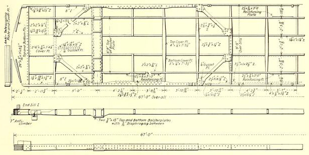
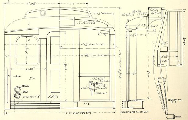
This car is designed as a side-girder structure in which the full height and length of the sides are available for resisting bending stresses, the door piers being used to transmit the stresses from the lower to the upper members. The underframe as a whole is designed merely to transmit the floor loads to the side sills, but the sections between the ends and bolsters, as hereinafter described, are especially stiffened and tied in with the side frame to take care of buffing shocks. The roof is practically free of all strains except that due to its own weight, and the carlins are little more than ties between the side girders.

Side Frame
The side frame is constructed of pressed steel panels, posts, pillars, etc. all of Grade B steel. The pressed steel panels provided at each side of each pair of side doors have openings with flanges to take the sash pressed into the same. The door side of these panels is reinforced with pressed steel posts to provide necessary stiffness, and the side adjacent to the windows has flanges pressed to form the sash stop, and at this side is riveted a pressed section of 1/8-in. Grade C steel to form the post. Horizontal stiffeners of 3/16-in. Grade C steel are provided on the inside of these panels in the door pockets, and a gusset plate is attached to the post at rear of the door pockets and to the adjoining crossbearers. Pressed sections are provided on the post adjacent to the bolster; also at the corner post under the first window; the latter to provide stiffness for the end of car and to serve as a protection against telescoping. Pressed reinforcing plates of 5/16-in. Grade C steel are used at the intersection of the door pocket panels at the end side doors and the side sills. Door headers of l/g-in. Grade B steel pressings are employed over each door opening, riveted to the adjoining panels and body plate. These headers serve to give the proper finish and to provide the reinforcement necessary to compensate for that part of the top plate which has to be cut away to make headroom.
The body plate is of pressed section, of 3/16-in. Grade C steel. At the door opening the body plate is cut and properly formed and reinforced. The sash rests, which are installed in short sections between the window posts, are of 1/8-in. Grade B steel, reinforced on the inside with 1/8-in. Grade C steel pressings fitted at the posts and connected thereto with connection pressings and splice bars. The outside sheets excepting the door pocket panels are of 3/32-in. Grade B steel. Wherever possible the joints are welded to insure maximum strength, homogeneity and watertightness. It will be noted from the foregoing description that there is practically no belt rail as the inside stiffeners serve the same purpose. This construction gives a smooth outer side with no ledges or other water-catching fixtures.
Of the accompanying sections taken through the side, the one marked "vertical section through main win dows" is of additional interest as showing the window construction adopted to avoid ledges for dust. By rounding off the edge, the conspicuous white line usually formed by frequent wiping will be avoided.

Underframe
The underframe includes two side sills and two center sills, each running practically the full length of the car in one piece. The side sills are 8-in., 11.25-1b. and the center sills 7-in., 14.75-lb. medium steel channels. The side sill channels are attached to the buffer channels and anti-telescoping plates with steel pressings as indicated on the plans. The center sill channels are secured to the buffer channel by connection angles and riveted to the top and bottom buffer or anti-telescoping plates. A cover plate 3/16 in. thick x 30 in. wide is provided on top of the center sill channels, extending from the antitelescoping plate to the bolster, riveted to the center sill channels; also secured to the anti-telescoping plates and to the bolster by riveting to the extension of thetop flange of the pressed diaphragms. Two 3/16-in. x 24-in. anti-telescoping plates are provided at each end of the car, located on the top and bottom of the center and buffer channels, riveted thereto and to the side sill channels. These plates extend over the buffer channel to provide for the installation of Hedley 7-in. anti-climbers and the buffer timbers. These anti-climbers are bolted through the buffer timber and channel with countersunk keyhead bolts. The buffer timbers and anti-telescoping plates are clamped together with round keyhead bolts, excepting under threshold plates, where they are countersunk into the anti-telescoping plate, but there is no permanent fastening between the anti-climbers and anti-telescoping plates. The foregoing anti-telescoping construction between end and bolster is designed to take care of extraordinary buffing shocks without excessive weight of material, and in combination with the diagonals noted in the following paragraph the entire framing strength is made available to resist collisions. Pressings have also been designed for carrying the draft gear attachments and with the 3/16-in. x 30-in. cover plate they form a box girder to reinforce the center sills.
At the end side doors the side sills are reinforced to take care of the break in the side girders required for the doors. This reinforcement comprises a 5/16-in. pressed steel shape and 1/2-in. x 6-in. cover plates, top and bottom, extending from the bolster itself to the second main cross-bearer from the bolster and riveted to the side sill. To stiffen the underframe laterally, diagonal braces are provided from the intersection of the center sill channels and cross-bearer, between the bolster and the end of the car, extending to the intersection of the bolster and side sill; also from the side sill at the intersection of the next adjoining cross-bearer and center sill toward the middle of the car. These braces are of 3/16-in. plate with ends flared to provide for proper fastening. Provision against the torsion of side sills by reason of eccentric loading is embodied in the reinforcements already described.
The main cross-bearers are built up of 3/16-in. steel diaphragm pressings, with top and bottom cover plates of the sizes shown. The intermediate cross-bearers are of 3/16-in. pressed steel diaphragms without cover plates. The plan of the underframe shows a number of minor features, such as stringers and cross-bearers for carrying the floor; also the 2 1/2-in. x 3/16-in. x 3-ft. reinforcing plates, which will take care of excessive standing loads in the seatless area opposite the side doors.
Bolsters and Bearings
The bolster is of the built-up type, consisting of two 3/8-in. x 15-in. steel plates on top and bottom with 5/16-in. pressed steel diaphragms between the plates. This double-plate section extends from the center outward for about two-thirds of the bolster length. The bolster is riveted to the side and center sills, and a vertical reinforcing flange is provided at the ends of the bolster and riveted to the adjacent post of the side frame.
The car-body center plates are made with two bronze friction disks, and the bearing surfaces of the steel center plate castings are burnished to avoid cutting. For reasons of truck design, the Stucki roller side bearings are of inverted form, the rack being installed on the truck and the plate on the car body. These bearings are of self-centering type, namely, as one side of the roller is heavier than the other the force of gravity rights the bearing as the car departs from curves.
End Framing
The end sheets are of 1/8-in. Grade B steel specially formed with openings for windows with flanges to take sash pressed into same and riveted to pressed posts at end doors and corners. The corner posts are built up of pressings; the outside post of 1/8-in. Grade B steel and the inside of 1/8-in. Grade C steel. The door posts are Grade C steel 3/16 in. thickness, and the inside door post on door pocket side are of pressed section 1/8-in. Grade B steel. Cast-steel connection castings are employed between the end door posts and buffer sills to resist telescoping, and reinforcements are also provided on the end sheets. The hood framing is built up of standerd structural steel shapes and plates.
Roof
The form of the roof is a compromise between the single arch and the monitor type, owing to the type of Perry "ingot-iron" ventilators used in the deck and to the need for maximum clearance in the tunnels. Inside the car, the effect is that of an Empire ceiling. The deck plate is of 1/16-in. ingot iron. The carlins are 3/32-in. Grade B steel pressed in one piece, flanged and attached to the body plate with pressed steel brackets. The upper deck roof sheets are of 1/16-in. "ingot iron" and extend in one piece across the entire width of the upper deck. Splices are made at carlins by lapping sheets, riveting to carlins and welding joints. These sheets are riveted longitudinally to the deck plate. The lower deck roof sheets are of 1/16-in. "ingot iron" fastened to the carlins and spliced in the same manner as the upper deck sheets. They are riveted longitudinally to the body plate, cutting out over the door openings. They are also riveted longitudinally to the deck plate. One-ply "Rubberoid" roofing is furnished between each member of the structure and the roof sheets, and the roof sheets are riveted to and spliced at all carlins, whether at splices or not. The hoods and the drip rails are of 1/16-in. "ingot iron." The gutters are of the same material and are soldered to the roof sheets.

Floor
The floor construction presents a most interesting novelty in that no floor is used under most of the seats. This plan saves appreciable weight and floor material; furthermore, it permits apparatus to be located to better advantage. Thus valves, governor, air-compressor intakes and other fittings can be placed in nooks protected from dust, water, etc., while still accessible for inspection. The seat supports form a box with pressed steel sides open at the bottom but with a 3/16-in. waterproof Agasote shield below the cushion to secure heat insulation. The floor sheets are of "Chanarch" 5/8-in. section No. 22 gage, galvanized sheet "ingot iron," laid on top of the floor stringers, riveted thereto and at all joints. A 7/8-in. ramp is provided at each side door. The floor covering is of "Flexolith," laid to a thickness of 3/8 in. above the top of the floor. After the flooring is thoroughly hardened, it receives two coats of a mixture containing one part linseed oil and three parts turpentine. At all sides and at seat risers, etc., a sanitary cove, 2 1/2-in. high, neatly rounded at corners, is provided, and all open spaces at the posts and sides of car are thoroughly sealed.
Doors and Sash
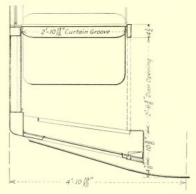
All doors are constructed of "ingot-iron" sheets. The door joints are welded and thoroughly sealed against moisture. The side and end doors slide into pockets and are hung on "Diamond" ball-bearing door hangers. A novelty in connection with the threshold plates is that the abrasive metal, which is of "Feralun" type, has been combined with the threshold plate and door guide, the abrasive metal being- used also for the door guides which are usually of cast iron. The portion of treads used as door guides has no abrasive surface. Door guides of pressed steel extend from the threshold plates into the door pockets. All side and end doors have an adjustable guide shoe to suit the threshold plates. Felt weather stripping is provided on the rear edge of each side and end door and reinforced sheet rubber at the top of all sliding doors and at the door jamb of the end doors. The end doors are equipped with Howard end door locks. The center dooi pockets are arranged for destination signs.
All sashes are of mahogany. Fixed sashes set in steel panels are 5/8-in. thick, but the stationary end sashes in steel panels, which have wired-glass are 3/4 in. thick; all other sash are 13/16 in. finished thickness. As in the present subway, the upper side sash is arranged to drop. The sashes on the inside of the door pockets are arranged to swing. Each upper side sash is provided with "Forsyth" metal weather strip and is equipped with O. M. Edwards' two sash catches and Edwards' compression spring rollers. Weather strips of velvet carpet are supplied at the top and bottom of the upper side sashes. All of the sash hardware is of bronze.
The curtain material is of double Pantasote with the Curtain Supply Company's friction type fixtures and Rex all-metal friction rollers at all windows except the side windows in the door panels.

Seats and Cabs
All the rattan seat cushions and backs are of Hale & Kilburn manufacture. The seat frames are constructed of light Grade A steel sheets. A support of shallow pan shape is built for each seat frame, flanged to support the “Chanarch” flooring at edges and to have a 2 1/2-in. sanitary cove around the entire seat base. The seat frames can be readily installed and removed from the car without in any way disturbing the flooring material or the interior finish. It is interesting to note that the seats, including height, shape and angles have the approval of the American Posture League. Cast-iron porcelain enameled grab handles of “Ellcon” make are provided on the seat framing. Porcelain enamel instead of bronze was selected for sanitary reasons as the metal is not kept clean so readily.
A cab is provided at two diagonally opposite corners of each car, arranged with a door hinged from the end door post and with a curtain in the rear partition, to form an inclosure for the motorman. When open for passengers the door swings to cover the control and air-brake operating valves at the end of the car, and the curtain in the rear partition is raised. The door is equipped with a double-acting latch with a lock to hold same in position both as made up for cab and as arranged for use of passengers. The motorman's seat is of pressed steel covered with hair felt and rattan. When not in use it is folded to make room for a regular passenger seat. When the latter is folded, the seat cushion is behind the back of the adjoining seat on the other side of the partition while the seat back is hinged to drop.
Headlining and Interior Side Sheathing
All side end and roof sheets, posts and pillars, as well as all other parts of car body, are provided with heat insulation of Johns-Manville "Salamander." This material is applied on a coat of wet freight car paint with crout nails spot-welded to the sheets. The headlining is of 3/16-in. "Agasote," the upper deck extending in one piece transversely and in seven sections longitudinally. The lower deck headlining is made in eight sections longitudinally with joints lining up with the joints in the upper deck ceiling. A transom conforming to the lower deck ceiling is provided transversely at each end of car. All joints of headlining are covered with drawn steel moldings, and held in place with oval head machine screws. A 3/16-in. wainscoting of "Agasote" is provided at the sides of the car between the posts. All sheets for interior finish, other than the headlining and wainscoting of "Agasote," are of Grade A steel. All drawn steel moldings are of Grade A material.
Miscellany
Grab handles of cold rolled steel with forged ends are used at the ends of the cars. Each end also has two safety gates which are arranged to hang between two adjoining cars. These gates have spring hinges to hold them in the outward position to insure self-coupling, thus avoiding the need for relying upon the guards to close the danger gaps between cars.
Spaces for advertising racks 11 in. wide over side doors and windcws, and of special sizes at the ends, are formed of drawn steel moldings. The standing areas inside the car are supplied with vertical stanchions and elevated horizontal railings of 1 5/8 in. and 15/16 in. outside diameter steel tubing enameled with porcelain.
 N. Y. M. Car—Transverse Section and Interior End Elevation. |
 N. Y. M. Car—Longitudinal and Side-Door Folding Seat. |
 N. Y. M. Car—Passenger Seat in Empty Cab. |
Motors, Control, Conduit and Collectors
Electric Railway Journal · Vol. 45, No. 11 · March 13, 1915 · pp 496-503.
Tapped-Field Motors Give Economical Operation in Both Local and Express Service -- The Control Ties in with the Auxiliary Circuits and Its Switches Are Placed in One Box to Obtain Lowest Weight and Simplest Inspection -- Conduit Runs Have Been Reduced by Eliminating Separate Conduits for Each of the Wires in the Main Circuits.

The motors, the control and the accessories of both on the New York Municipal car embody the same principle of progress that characterizes the features of design and equipment which have been previously described in these columns. (See New York Municipal Car articles on "Design," "Body" and "Trucks, Brake Rigging and Draft Gear," June 6, June 13, and Dec. 26, 1914, respectively.) As the following paragraphs will show, the New York Municipal Railway Corporation has not only taken advantage of the latest advances in the art but it has also set up new standards and devised new practices which will accrue to the benefit of other electric railway operators.
Character of Forthcoming Service
To appreciate the reason for electing to use the tap-field motor in the forthcoming service it is well to point out that three distinct services -- local, express and a combination or these two -- are contemplated. For purely local runs the schedule speed will be 15 m.p.h. with an average station stop of 20 seconds, and for purely express service the speed will be 25 m.p.h. with an average stop of 30 seconds.
On a typical local run like that of Fifty-ninth Street, New York, to Coney Island, by way of the Manhattan Bridge and Brighton Beach line, the shortest distance between stations will be 1100 ft., the longest 6220 ft., exclusive of the Manhattan Bridge, and the average 2430 ft. The length of this run will be 68,090 ft. plus the 10,560 ft. of the Manhattan Bridge.
On a typical express run like that from Forty-eighth Street, New York, to Sheepshead Bay, the shortest distance between stations will be 3930 ft., the longest, 9870 ft. and the average 7230 ft. The length of this run will be 43,380 ft.
On a typical combined express and local run like that from Forty-eighth Street, New York, to Coney Island via a 7000-ft. tunnel and the Brighton Beach line the shortest distance between stations will be 1263 ft., the longest, 9870 ft. and the average 4573 ft. The length of the run will be 82,327 ft. In general the local runs will be longer but the express runs shorter than on the present rapid transit lines of New York.
It was obvious that the tap-field motor was ideal for running conditions of the character described, inasmuch as such a motor could b6 run on full field in local service and on tapped field in express service. Self-ventilation was also desirable for the motor because the limiting weight per driving axle made it essential to combine greatest output with least weight. Besides this, the motor equipments will be kept in almost continuous service, as some of them will have only three minutes lay-over at terminals during continuous working periods of eighteen hours. Local trains will consist of two to five cars each and express trains of two to eight cars each.
The Motor
The motor selected for the first 100 cars (two per car) is the GE-248-A commutating pole type with fan assembled on the pinion end of the armature head. The frames are also constructed with openings in the covers. The motor weight, including the gear, pinion and gear case, is 5975 lb. The motor, under the A. I. E. E. standards, has an hourly rating of 160 hp at 600 volts.
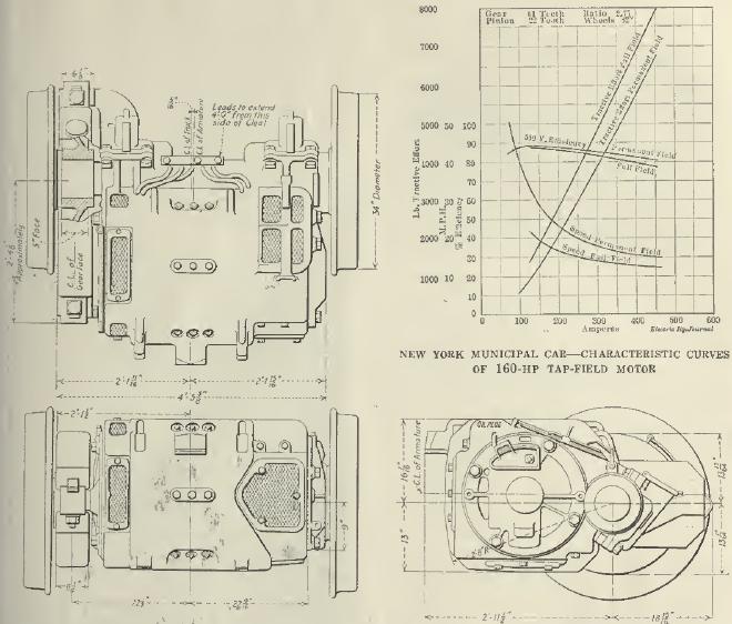
This motor must operate over a voltage range of 450 to 750 volts, and its continuous ratings up to 600 volts are as follows: 140 amp at 300 volts, 147 amp at 400 volts, 154 amp at 500 volts and 157 amp at 600 volts, with a temperature rise in the windings not exceeding 75 deg. Cent, when all the covers are off. The general characteristics are shown in the curves on page 497. The ability of two of these motors to propel at an average of 550 volts a car weighing 113,000 lb. fully-loaded (200 passengers at 140 lb. each) is based on an assumed adhesion of 27.5 per cent between the driving wheels and rails, a curve resistance of 0.8 lb. per ton per degree of curvature and the following train resistance values:
| M.P.H. | Pounds Per Ton | M.P.H. | Pounds Per Ton | |
| 8 | 7.26 | 30 | 11.86 | |
| 10 | 7.45 | 32 | 12.21 | |
| 12 | 7.81 | 34 | 12.76 | |
| 14 | 8.14 | 36 | 13.20 | |
| 16 | 8.47 | 38 | 13.75 | |
| 18 | 8.91 | 40 | 14.19 | |
| 20 | 9.35 | 42 | 14.74 | |
| 22 | 9.79 | 44 | 15.29 | |
| 24 | 10.23 | 46 | 15.95 | |
| 26 | 10.72 | 48 | 16.50 | |
| 28 | 11.22 | 50 | 17.05 |
The train resistance values were derived from tests made on near-by rapid transit lines.
The motor frame is of the box type, of cast steel fitted with a removable wearing plate of hardened steel on the motor suspension lug, and with cast bales for handling the completely assembled motor. A feature in the construction of the field coils is that their final coating of insulating compound has the unusually high melting point of 135 deg. Cent. Other features are that metal shields are fastened on the inner perimeter of the coils to prevent chafing on the pole pieces and that all the field coils are held in place against flat steel springs to prevent their movement in service.
 NEW YORK MUNICIPAL CAR -- AXLE SIDE, COMMUTATOR END OF MOTOR. |
NEW YORK MUNICIPAL CAR -- SUSPENSION SIDE, PINION END OF MOTOR. |
NEW YORK MUNICIPAL CAR -- INTERIOR OF CONTROL CAB WITH CURTAIN RAISED. Note projection of motorman's seat, which is hinged to back of passenger seat. |
The brush-holders, which are designed to permit 1-in. safe radial wear of the commutator, have shunts so constructed that they will not have any wearing action against the brush-holder casting. The brushes are placed in staggered relation, and their tension is adjustable between 3 lb. and 10 lb. The mica insulation between the commutator bars is cut 3/64 in. and extends 1/8 in. back of the commutator neck.
Lubrication has received special attention in the design of this motor. The bearing housings are supplied with separate oil gage wells and waste chambers. By removing the wooden plug of the external well and inserting a gaging ruler, the shopman can determine the quantity of oil in the gage well and if necessary can replenish the oil supply without exposing the lubricating packing to dust or needless handling. Oil deflectors are provided on the armature shaft to prevent the oil from working into the motor windings, onto the commutator or onto the brush-holders. The housings also contain grooves for conducting overflow oil to an auxiliary chamber on the outside of the motor. Wool waste is used in both the armature and axle bearings.
As the motors are of self-ventilating type special care was taken to prevent, as far as possible, dust from entering the bearings or wearing surfaces, dust guards being used at exposed points. Further, the axles are entirely inclosed in a shield to exclude dust from the inner ends of the bearings.
Safety straps are provided to prevent the fall of the lower half of the gear case should the nuts from the clamping bolts be lost. The gears and pinions are made of Grade F forged steel and have a ratio of 61:22. The gearing has teeth with a stub profile to meet the severe conditions anticipated.
Control
The control system is designated by its manufacturer, the Westinghouse Electric & Manufacturing Company, as Type 100 ABF. While it represents no great change in principle from a combination of the Westinghouse ABF and PK types of control, old elements have been combined in new ways and special duties have been added, as hereinafter detailed.
In this control the following features have been met for the first time:
First -- Combined design, which includes provision for the use of the storage battery furnished for emergency car lighting, common use of apparatus of the brake and electrical equipment, provision for signal and other functions in the control equipment and particular adaptability to the use of automatic electric couplers.
Second -- Selective acceleration, the current input being determined by the load.
Third -- Operation of sixteen motor cars from a common train line.
Fourth -- Use of a common eighteen-wire train line, including provision for auxiliary circuits.
Fifth -- The combination of all control apparatus in a single box to obtain the lowest weight and the simplest inspection.
The company considered also the use of control current taken direct from the 600-volt line, but it decided in favor of the 34-volt battery train line for the following reasons:
First -- In a 600-volt train line if the power is off the first car, none is available for operating the control for the rest of the train.
Second -- Since the brake actuating circuits should be independent of line voltage, it would be objectionable to have a 600-volt control circuit in a common train line with the low-voltage brake circuit.
Third -- The use of the battery permits the bucking of motors for emergency braking if the line power fails.
Fourth -- Low voltage secures greater freedom than line voltage from derangement of circuits such as those due to grounding and short-circuits.
Fifth -- A material saving in the cost of control power is secured.
Sixth -- Installation is simpler, with the elimination of switches, fuses and resistance elements.
Seventh -- There is greater certainty of reliable operation of a low voltage automatic electric coupler.
Eighth -- There are no high-voltage connections in the control apparatus above the floor of the car.
Ninth -- The storage battery required for emergency lighting and brake control can, without change, supply power for the control purposes.
Tenth -- Simpler design and installation of accessory apparatus, such as automatic electric couplers, is secured.
Eleventh -- The form and design of apparatus and contacts for handling the control circuit are simpler, with the elimination of burnouts on the master controllers and interlock fingers.
Battery and Train Line
In order to make the battery circuit available for signal lights, door circuit interlocks and to insure correct operation for a maximum possible train length of 1075 ft. the control battery had to be raised from the old standard of 14 volts to 34 volts. The cross-section of the train wires was also increased to avoid excessive drop, each conductor in the eighteen-conductor train line consisting of seven strands of No. 24 wire. The door signal circuit involves the use of train wires which extend in series to a distance equivalent to more than twice the train length.
All control circuits are energized from storage batteries on each car, all of which are permanently grounded on the negative side. The valve magnets require approximately 1.5 amp per car when the motors are in series, and 1.8 amp per car when the motors are in parallel. The storage battery has an estimated capacity of not less than 20 amp-hr. Charging current is available from the compressor during operation. Therefore the battery is mainly for emergency lighting, end and rear marker lights and for the operation of the electro-pneumatic brake circuit.
A total of eighteen wires is included in the train line, disposed as follows: Battery positive, one; brakes and speed control, five; local signal circuits between cars, one; starting signal and door interlock circuits, one; control circuits, seven; extra, three; total, eighteen.
The train line has three junction boxes, and includes wires for the operation of the magnet valves of the air-brake system, suitable outlets being provided for the circuits to the brake apparatus in the center of the car, and for the engineer's valves at each end. This includes provision for the automatic speed control device ind for synchronizing the compressor governors.
The air supply for the operation of the switching apparatus and the reverser of the control box is taken from the common air brake supply outside the reducing valve of the air-brake system.
With the reverse drum of the master controller in either the forward or the reverse position, the battery plus circuit is completed to the main drum of the controller, which in turn energizes the series wire, the progression wire and the multiple wire, on the first, second and third notches of the controller, respectively. On the first notch the main drum also completes the battery plus circuit for the operation of the reverser magnets to throw the reverse drum to the desired position. The interlocking on the main switches, reversers and the commutating switch is such that all operation must take place in the sequence indicated, and all main circuit apparatus is protected against injury due to the false operation of any part. It is necessary to complete the circuit for three wires at the master controller before power can be applied to the motors. These wires are the series wire, one or the other of the reversing wires, and the wire which is the return circuit for all magnet coils. With this provision and low-voltage control practically absolute insurance is given against any possibility of a faulty connection in the train line which might cause the operation of the train to be taken from the control of the motorman.
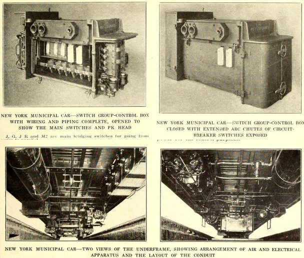
The Control Box
Another innovation in control equipment was promoted by the customer's specification that all of the usual under-car motive power apparatus, namely, unit switches, commutating switch, reverser, circuit-breaker and relays should be mounted in one box to effect a large saving in the length, weight and cost of conduit; and also to simplify inspection and to avoid shopping a car for several days when overhauling of the main control parts is required.
This control box includes the following parts: Two unit switches acting as circuit breakers; four unit switches for series paralleling the motor; one drum type reverser; one drum type commutating switch; one limit switch; one overload trip relay; one main circuit terminal board; one control circuit terminal board.
Unit construction is the basis of the switch design, and each switch, magnet, jacket and cylinder may be removed independently of the other parts of the apparatus.
The control is so designed that the upper compartment of the control box accommodates a main circuit junction box. By removing the motor leads and resistance leads from the terminal board and from a few of the studs the main assembly can be lowered from the car by loosening four supporting bolts, following which a new group may be substituted. It is estimated that within thirty minutes one man with the proper hoisting equipment can remove and replace the switch group.
The top frame of the switch group box is constructed to hang from the center sills of the car underframe by means of four lugs, no hanger straps being used. As shown in one of the under-car views, this box is mounted under the center of the car in such fashion that a man can walk around it on all sides. He is therefore able to remove with ease the doors which cover each compartment and then inspect the group and unit switches and the terminal board above them.
The general layout of the equipment in the control box is shown in part in an accompanying halftone and drawing, and further data on the location of individual parts are presented in the following paragraphs.
The current limit relay is placed alongside the reverser while the 34-volt terminal board is placed beneath the limit switch at the reverser end of the switch group. To this board is brought the conduit through which the control wires are run. All the necessary wiring connections for the motive power circuits were made at the factory, the only job left to the user being the attachment of ten motor leads, eight resistance leads, eight control wires, one ground lead and one trolley lead.
The overload trip relay is mounted next to the limit switch and consists of a plunger actuated by an arm which lifts at a predetermined current in the trip coil. The relay is calibrated in five steps at 100-amp intervals, starting with 450 amp which is approximately twice the one-hour rating of the motor. Contact disks on the plunger open the control circuits to all switches, and these circuits are re-established by unlatching the plunger by means of the reset coil, which may be energized by pressing a button in the top of the master controller after the main handle has been returned to the off position.
On the opposite end of the group of switches is mounted the PK head. The double air cylinder operating this drum is controlled by the unbalanced pressure system whereby the drum is moved from notch to notch under the control of the limit switch. Full pressure of air is maintained in both cylinders, and is intermittently exhausted from one side in order to allow the drum to move from notch to notch. After the drum has advanced, cutting out resistance and changing the field circuits to normal field in series, it returns to the first position after the closing of the J switch and advances again after the bridging and parallel connection has been made by the unit switches.
It will be noted that in normal operation no arcs can be broken on the commutating switch and drum, since the main switches are so arranged that no current is passing through the resistance fingers at a time when they are leaving the ground. However, a magnetic blow-out is provided to protect the field fingers in case a motor-lead becomes open-circuited. In passing from series to parallel, the J switch is closed, thus short-circuiting all resistance before the drum falls back to the first position, and in shutting off from any position on the master controller all the unit switches open before the drum starts to move backward.
For the specific manipulation of the main circuits, six steps are provided in series and four in multiple, with closed circuit or bridging transition between series and multiple to insure uniform acceleration. Each contact with this method carries the current for a single motor only. The two switches which are used as circuit breakers are isolated and have a separate vent for the expulsion of the arc to, atmosphere. They differ from the other unit switches only in the use of extended arc chutes, thus making all switch parts interchangeable. The remaining four unit switches establish the motor circuit connection to secure the series-parallel connection. In the operation of the overload trip all these switches open at the same time.
For the minor changes in the motor circuit the PK head is used. The PK contacts care simply for changes in resistance and for the changes in the field connections. They carry current for a single motor only. The adoption of this modified form of PK equipment eliminated eight control switches, made possible the use of a control box 4 ft. in length instead of 6 ft., and reduced the weight of the switch group to 850 lb.
The course of the circuit is as follows:
From the 500-amp position of the knife-switch connection to the current collectors, the circuit passes directly to the control box and to the overload trip. From the trip the circuit divides, passing through the two circuit-breaker switches, and then through each of the two motors with their starting resistance, and to the ground connection on the car body.
As shown on the main schematic diagram the circuit passes through LS-1 on the first notch; through the switching resistance; the No. 1 motor; the main starting resistance; through the JR switch; the resistance for the No. 2 motor, and through the No. 2 motor and the limit switch to ground. LS-2 closes for the second notch, and the remaining notches to full series are secured by cutting out the main starting resistance.
In passing from series to parallel, the bridging transition circuit is formed through the switches M-2, J and G. After the J switch is opened, the motors are in parallel with resistance, the resistance is then cut out step by step and the field connections changed to normal field in the same manner as was done in the series connection.
The line relay, which is placed on a switchboard located between the two center doors instead of being in the control box, is energized directly from the 600-volt circuit. Its contact disk is so connected in the control circuit that all unit switches open whenever power fails, permitting the control to advance in regular sequence when power is restored, without the master controller being returned to the off position. The relay is so adjusted that it will lift at approximately 350 volts and drop at approximately 150 volts. With this range, the relay has sufficient travel to insure positive action of the contacts and contact disk. The line relay also has auxiliary contacts to light the emergency lamps.
Master Controller
The master controller is equipped with the usual three notches for switching, series and multiple positions and with a separate reversing drum and the usual deadman's handle. The movement of the reverser handle to an operating position energizes the control-circuit supply, thereby eliminating an auxiliary cut-out switch. Inserted in the case at the right-hand side of the controller are an emergency cut-out switch for the 34-volt control circuit, a circuit-breaker reset button, a line relay cut-out button and marker-light switch button.
The deadman's handle on this controller acts by the application of battery current to the emergency train line wire. This application instantly energizes all emergency valves in the train upon the relaxation of the motorman's grasp at any position of the handle, whether the reverser is forward or reverse. By the same operation a special device completely cuts off power from the propulsion circuits.
The marker-light switch was added to the controller by the New York Municipal Railway. The signal lights which indicate that all doors have been closed are also installed in the master controller to avoid too many individual pieces of apparatus in the cab.
In addition to the usual contacts and fingers for the control circuit, the master controller has interlock contacts mounted on the reversing-drum shaft to provide for three auxiliary contacts. Two of these contacts are for signals and one is for tail-lights. These unusual features will be described in a later article in connection with the door signals, marker lights and train line coupler. The reverse drum acts as a switch to close the battery circuit to the control.
Still another new feature is that both polarities of the control circuits are broken at the controller. This is accomplished by running an extra train line wire for the negative side of the magnet coils. As no attempt has been made to ground the return circuit of the control, local grounds cannot create false circuits or cause false operation.
The line relay cut-out will permit the feeding up of the control when power is off the line and the bucking of the motors, as an emergency method of stopping the train should power be off the line and the air brake fail.
Selective Acceleration
In order to obtain the same rate of acceleration with all passenger loads from minima to maxima there is provided an extra winding on the limit switch which modifies the current input to the motors. The amount of current through this winding is controlled from a switch operated in connection with the empty and load brake mechanism. The adjustment of this mechanism corresponds directly to the deflection of the bolster springs under load.
Conduit
In the earlier installations of equipment separate conduits were used for each of the wires in the main circuits. In the present installation, however, multi-conductor cables are used. Consequently one large conduit pipe serves for each set of motor leads. Likewise, all resistance leads are formed into a cable and are carried from the switch group to the resistors through a single conduit with a Crouse-Hinds eight-conductor outlet. In order to reduce the weight of the conduit itself, material of the following character was used: For straight runs inside the car, circular steel tubing of 1/32-in. wall, inside diameter corresponding to standard pipe sizes, fitted at each end with one Ellcon conduit fitting, lock nuts and spring lock washers; for straight runs under the car sherardized steel tube with suitable thickness of wall and inside diameter to correspond to standard; pipe size fitted at each end with one Ellcon conduit fitting, lock-nuts and spring lock washers; for runs requiring bends, "Sherarduct" with lock-nuts and spring lock washers. By the use of this system of conduit, the weight was reduced to a great extent.
Third-Rail Collector and Knife Switch
The current collector is the usual type of overrunning shoe with rack adjustment at the ends but with a bolt adjustment in the center to take care of finer adjustments within a range of 1 in. The terminals are somewhat unusual in having a taper fit so that by removing a nut the connection may be slipped off very readily. In order to eliminate the breakage of fuses and connections due to vibration, the fuse box is spring-supported. Another feature is that the cover of the box is formed of a single arch of Hemmit molded insulation. Instead of building the box of wood with joints and fastenings, in the present construction only the base of the box is of wood, and this is covered with transite. The shoe beam is supported from the journal boxes with proper link action for any difference in movement between the two boxes from which it is carried. It has no permanent fastenings but is slipped into 1-5/8-in. deep side pockets on the side of each box. Between each shoe-beam rack and journal box is a compression spring to prevent rattling of the beam. Armored cable is used for the connections to the car body, but rigid conduit is employed as the conductor between the shoe-beams of the same truck. Castle nuts with cotters are used throughout.
In conclusion it should be noted that the main knife switch not only has a 500-amp position for the connection to the current collectors described, but also a 75-amp position. With the switch in the 75-amp position the light, compressor and heater circuits are connected to an inspection attachment within the switch box, through which line voltage may be plugged from any convenient point for inspection purposes when it is desired to have the source of power disconnected from the main circuit. This main knife switch is of single-pole double-throw break type.

NEW YORK MUNICIPAL CAR -- ORIGINAL SCHEMATIC LAYOUT OF EQUIPMENT AND CONNECTIONS TO MASTER CONTROLLERS AS SUBMITTED BY THE MAKER; THE LAYOUT ON THE CAR IS SOMEWHAT DIFFERENT, BUT THE EQUIPMENT IS THE SAME.

NEW YORK MUNICIPAL CAR -- OUTLINES OF SWITCH GROUP, PK HEAD AND REVERSER.

NEW YORK MUNICIPAL CAR -- SIDE ELEVATION OF COMMUTATING SWITCH -- SCHEMATIC DIAGRAM OF MAIN CIRCUITS AND SEQUENCE OF SWITCHES.

NEW YORK MUNICIPAL CAR -- DETAILS OF THIRD-RAIL CURRENT COLLECTOR AND SPRING-SUPPORTED FUSE BOX MADE WITH COVER OF MOLDED INSULATION.

NEW YORK MUNICIPAL CAR -- MOTOR TRUCK CARRYING FUSE BOX WITH COVER OF MOLDED INSULATION.
The Lighting
Electric Railway Journal · Vol. 45, No. 13 · March 27, 1915 · pp 614-618.
Many Lighting Combinations Were Tried in a Full-Size Template Car, Resulting in the Choice of Fifteen 56-Watt Bowl Frosted Tungsten Lamps along the Car Center Line, Besides Emergency Lamps.
By W. G. Gove, Engineer of Car Equipment, New York Municipal Railway Corporation, and L. C. Porter, Edison Lamp Works, General Electric Company, Harrison, N. J. Abstract of a paper entitled "A Practical Study of Car Lighting Problems," read at a meeting of the New York Section of the Illuminating Engineering Society, March 11, 1915.
Not the least of the advanced equipment of the New York Municipal car is its lighting. Many new problems had to be solved to meet satisfactorily the following desiderata: (1) Quantity of light; it is desirable to have an average intensity of not less than 3 foot-candles on a horizontal plane 42 in. above the floor, at 85 per cent normal voltage. (2) General effect and appearance of lighting system with lamps lighted or extinguished. (3) Lack of eyestrain for both seated and standing passengers, involving not only intensity and direction of light, but also glare and possible shadows thrown by standing passengers on the reading matter of seated passengers. (4) Efficiency. (5) Installation and maintenance expense. (6) Depreciation of equipment in service.
To study these problems tests were conducted in a full-sized model car. This car was 67 ft. 3 in. over all, 9 ft. 10 in. wide and 12 ft. 3 in. high. The interior dimensions were 65 ft. long and 9 ft. wide. The interior finish was white enameled headlining and walls down to the window sills. Below the sills the walls were painted gray. The floor was concrete and the seats were upholstered in yellow rattan.
Photometer tests were taken to supplement such data as observation of the general appearance, installation and maintenance cost figures, etc. The photometric measurements were not made to compare the efficiency of any particular types of illuminating devices or accessories thereto, though the average intensities obtained were used in securing the relative utilization efficiencies.
In making the photometer tests stations were chosen 2 ft. apart in a horizontal plane 42 in. above the car floor, over one-fourth of the floor area. The entire car, however, was equipped with lighting units. Five readings were taken at each station, on a portable photometer, recalibrated before each test. To make one reading comparable with any other, simultaneous voltage readings were taken, as constant voltage was found to be impracticable. Each photometer reading was corrected to normal voltage from the characteristic curves of the lamp and the five corrected readings averaged to obtain the station value. In obtaining the average intensity for the entire car, weight was given the stations in proportion to the area covered. The illumination values were also calculated for 85 per cent normal voltage. The same lamps, as far as practicable, were used in the various reflector equipments.
It was decided before the tests started that tungsten filament lamps would be used for illuminants, the question being what was the best method of applying the lamps. Three systems of illumination were tried out, namely, direct lighting, semi-indirect lighting and totally indirect lighting. To carry on the tests the interior construction of the car was altered when this was necessary.
Photographs of the interior of the car were taken with the lamps burning. The exposures were timed to exactly two minutes. These photographs have no bearing on the photometric readings, except to indicate in a comparative way the high and low lighting throughout the car.
Direct Lighting Tests
The direct lighting tests made were as follows: No. 1. -- The lighting units consisted of a single row of fourteen 6-in. opal glass reflectors (Fig. 9) mounted along the center line of the ceiling and spaced as shown in Fig. 1. Ten reflectors were equipped with 56-watt clear bulb tungsten lamps and four with 10-watt clear bulb tungsten emergency lamps. The light distribution, Fig. 1, was good, though it had points of high intensity under the emergency lamps, due to the small lamp in the large reflector. No bare lamp filaments were visible along the normal line of vision. The efficiency of the system was high, installation costs -- on account of the single row of large units -- were low, and maintenance was good, the smooth surface of the reflectors facilitating rapid cleaning. The general appearance in the car was pleasing (Fig. 15) and the illumination good, averaging 5.7 foot-candles at normal and 3.2 at 85 per cent voltage, with an energy consumption of 1.03 watts per square foot. There were 5.54 effective lumens per watt and the effective utilization efficiency was 68.7 per cent. The utilization efficiency in an ordinary dark yellow car with similar equipment is about 30 per cent, showing the great advantage of the white enamel interior finish. No. 2. -- The second test. Fig. 2, was similar to the first, except that clear prismatic reflectors were used. The change of reflectors raised the average foot-candle intensity to 6.1 at normal and 3.4 at 85 per cent voltage. The effective lumens per watt were increased to 5.90 and the utilization efficiency to 73.2 per cent. Maintenance would be slightly higher, due to cleaning the prismatic glass. There was also a little more glare, though not an objectionable amount.
No. 3. -- In the third test five 94-watt clear tungsten filament lamps, equipped with clear prismatic reflectors, were located in a single row down the center line of the ceiling. Four 10-watt tungsten emergency lamps in clear prismatic reflectors were located between these. The resultant average intensity in the car body was good, but due to the relatively low hanging height and wide spacing of the units the distribution was very uneven (Fig. 3). The installation and maintenance of the system would be low, on account of the small number of large units to install and clean. The average foot-candles obtained were 5.0 at normal and 2.8 at 85 per cent voltage. The energy consumption was 0.87 watt per square foot; the effective lumens per watt were 5.75; and the effective utilization efficiency was 71.5 per cent.
Semi-Indirect Lighting Tests
No. 1.-- A very interesting method of lighting was used in the first semi-indirect lighting test. Twelve special 80-watt 95-volt turnip-shaped tungsten lamps, opal-dipped over the tip half, were installed down .the center line of the ceiling. Each lamp was suspended by an inverted white enameled cone, shown in Fig. 11. Three 10-watt tungsten emergency lamps were also used in small rosettes. The 80-watt lamps were connected six in series. All of the filament of the 80-watt lamps was located below the center of the bulb ; hence, none of it was in the line of vision. The opal on the lower half of the bulb served to protect the passengers' eyes from the glare of the bare filament and to reflect the light up to the ceiling. This system eliminated reflectors, special holders and other accessory equipment, thus lowering both installation and maintenance costs. The average intensity was 7.7 foot-candles at normal and 5.1 at 85 per cent voltage. The energy consumption was 1.69 watts per square foot, the effective lumens per watt 4.65 and the utilization efficiency 58.4 per cent.
No. 2. -- In the second semi-indirect lighting test a novel equipment was used (Fig. 10). Ten 56-watt clear tungsten lamps were located on the center line of the ceiling, supplemented by four 10-watt tungsten emergency lamps. At 6 in. below the ceiling, and extending the entire length of the car, was suspended a reflector consisting of a white enameled board 11 in. wide, convex on a 16-in. radius. The bowls of the 56-watt lamps extended through holes cut in this reflector. Under each hole was fastened a white glass dish to diffuse the glare of the bare filament. The plan was to utilize as much as possible of the direct light from the lamp, to illuminate the advertising signs ; the indirect light to give even distribution and the direct light to brighten up the under side of the reflectors. The light distribution was good, but the intensity low, averaging 3.9 foot-candles at normal and 2.2 at 85 per cent voltage. The watts per square foot were 1.03, effective lumens per watt 3.81, and the effective utilization efficiency was 47.2 per cent. The illumination was pleasant, but the appearance of the lighting equipment was rather crude, suggesting a watering trough down the center of the car. While both sides of the reflector and the ceiling were painted alike, the under side of the reflector appeared gray, due to the lower intensity of light on it. Another test with the interior finish silver gray instead of white lowered the efficiency about 10 per cent.
The next semi-indirect equipment tested consisted of ten 94-watt tungsten lamps equipped with five 13-in. glass bowls, mounted down the center line of the ceiling. There were two 94- watt lamps and one 10- watt emergency lamp in each bowl. The bowls were hinged to allow lowering for cleaning and lamp replacement. The bowls were suspended with their tops located 12 in. below the center of the ceiling. The illumination from this system was very uneven, being high directly under the units and low between them (Fig. 5). The average intensity was 5.7 and 3.2 foot-candles at normal and 85 per cent voltage respectively; watts per square foot 1.69, effective lumens per watt 3.36, and effective utilization efficiency 41.5 per cent.
To determine the effect of the shape of the ceiling on the light distribution, a special headlining consisting of a white enameled insert, having a 3-ft. span on an 18-in. radius, was inserted and the test repeated (Fig. 16). This raised the average foot-candles to 6.1 and 3.4 at normal and 85 per cent voltage respectively, effective lumens per watt to 3.62, and the utilization efficiency to 44.7 per cent.
The insert was then removed and the test repeated with a different spacing of the units. This resulted in a little improvement in distribution. The principal trouble was that the car headroom was not sufficient to allow the lighting units to be hung the proper distance below the ceiling.
The next equipment tested required special reflecting devices. Ten 56-watt clear tungsten lamps were located in a single line down the center of the ceiling, with five 10-watt all-frosted emergency lamps in rosettes between them. Each 56-watt lamp was equipped with a screen made from a circular piece of glass bent over a cylinder (Fig. 14). This gave a screen 11 in. long x 8 in. wide x 3 in. deep. When these screens were hung beneath the lamps with their open ends toward the side of the car, it was possible to see the lamp filaments from any part of the passenger car body; at the same time the direct light from a considerable portion of the lamp fell on the ceiling and reached the reading plane with but one reflection, making the system fairly efficient. The distribution lengthwise of the car was even, though the outboard seats received considerably less light than the center aisle of the car. The average intensity was 4.8 and 2.7 foot-candles at normal and 85 per cent voltage, the energy consumption 1.04 watts per square foot, effective lumens per watt 4.63, and effective utilization 57.6 per cent. The chief advantage of this equipment was the ease with which the reflectors could be cleaned.
Totally Indirect Tests
No. 1. -- The first totally indirect equipment tried consisted of eight special indirect fixtures, these being white porcelain enameled on steel, 15-1/2 in. in diameter and 5-1/2 in. deep. Each fixture contained three 36-watt tungsten lamps mounted vertically. The fixtures were hung in a single row down the center line of the ceiling, the tops of the reflectors being 13 in. below the ceiling. The spacing of the units is shown on Fig. 6. The resultant illumination was uniform and of fairly good in- tensity, averaging 5.1 and 3.2 foot-candles at normal and 85 per cent voltage, for an energy consumption of 1.47 watts per square foot. The effective lumens per watt were 3.43 and the effective utilization efficiency was 46.3 per cent. The chief drawback of these fixtures was their liability to catch and collect much dirt, thus materially reducing their efficiency; also to obtain good distribution it was necessary to hang them so low that they might be in the way of tall passengers.
No. 2. -- To get away from a low fixture in the center line of the car, the next equipment tested consisted of twenty 36-watt tungsten lamps in indirect reflectors. These were mounted in two rows of ten each on the sides of the car, just above the deck sill between the ventilators, as shown in Fig. 17. Five 10-watt frosted lamps in rosettes were mounted on the ceiling for emergency lights. The 36-watt lamps were mounted horizontally with their centers 7 ft. 4 in. above the floor. The spacing of the lighting units and the distribution therefrom is shown in Fig. 7. The resultant illumination was of low intensity, averaging 3.5 and 2.2 foot-candles at normal and 85 per cent voltage. The wattage consumption was 1.32 per square foot, effective lumens per watt were 2.67, and effective utilization efficiency 36.3 per cent. The main objection was keeping the reflectors clean.
No. 3. -- The last test was made on twelve 94-watt tungsten lamps in indirect reflectors and five 10-watt emergency lamps in rosettes, located down the center line of the ceiling. To get maximum headroom for these reflectors and still have them out of the way of passengers, special inverted cone-shaped containers for the reflectors were built into the stanchions along the center line of the car (Fig. 18). Unfortunately the construction of the car necessitated spacing the units rather far apart, so that uneven illumination resulted. In addition to the bowls, smaller inverted bowls were mounted on the horizontal grab rails, at points shown in Fig. 8. Each of these contained one 94-watt tungsten lamp, making a total of twelve 94-watt and five 10-watt lamps in the car. The average foot-candles were 8.5 and 4.7 at normal and 85 per cent voltage, watts per square foot 2.01, effective lumens per watt 4.21, and the utilization efficiency was 53.4 per cent. Much difficulty would be experienced in keeping this equipment clean.
Considerations Which Fixed The Choice
General Effect and Appearance. -- The general effect and appearance of each system under test were judged by comparison with present methods of car lighting for similar service, namely, with the use of tungsten lamps but without reflectors. Under this item was also considered the effect of the distribution of light on the various parts of the car.
Lack of Eyestrain. -- The effect of the light on the eyes was particularly noted by a large number of observers.
Ease in Reading for Seated and Standing Passengers. -- Particular attention was given to the possible shadows thrown on reading matter of seated passengers by passengers standing in a crowded car. In some cases it was found that passengers could obtain proper light in any position; in others it was necessary for them to move in their seats, often to uncomfortable positions, to obtain proper light.
Efficiency of System. -- The efficiencies of the systems tested differed widely. In some cases this was largely due to the type of reflector used; in others to the position of the reflector, shape of the ceiling, etc. In several tests it was evident that improvement could be made by changes.
Maintenance. -- The question of maintenance was serious. Some of the most desirable arrangements of reflectors and lights were handicapped by the dust problem. With a large number of small units this difficulty increases.
Energy Consumption. -- To secure a reasonable operating cost, low energy consumption was one of the important factors. The indirect system of lighting required considerably more power than the direct, while the semi-indirect came between these two.
Depreciation. -- The relative loss of reflecting power, due to accumulation of dust on the various types of reflectors, also received consideration.
Emergency Lighting. -- It was decided that sufficient light would be obtained from the emergency lamps to permit clearly distinguishing people and various objects in the car with the main lamps extinguished.
A thorough study finally led to the adoption of a single line of fifteen 56-watt bowl-frosted tungsten lamps placed symmetrically down the center line of the ceiling, equipped with reflectors, as shown in Fig. 19, supplemented by six 10-watt all-frosted round-bulb tungsten emergency lamps. One big unit was placed on each end bulkhead of the car to bring up the illumination at these points. This system was chosen as the one containing the highest percentage of satisfactory illumination, low energy consumption, low maintenance and upkeep and pleasing appearance.
The emergency lamps were placed in rosettes, one being located on the side wall over each pair of doors. These lamps do not burn while there is power on the line, but the instant that fails they are automatically thrown onto a storage battery.
In the car as finally equipped the illumination averaged 5.94 foot-candles at normal and 3.85 at 85 per cent voltage, the energy consumption was 1.44 watts per square foot, effective lumens per watt 4.14, and the utilization efficiency 50.6 per cent. These data are not comparable with the other tests, due to the use of bowl frosted lamps (instead of clear), also a larger number and different arrangement of lighting units.
It was interesting to note that the low intensities of illumination, at stations 7 and 17, were opposite the entrance doors, which are dark green, in comparison to the white finish between doors. The curves were slightly high at stations 2, 3 and 4, due to the fact that the end lamps are located on the bulkheads considerably lower than the rest of the lamps in the car.
On the whole, the illumination is remarkably soft, even and pleasing. It is not possible to note any unevenness with the naked eye. The use of bowl-frosted lamps lowers the efficiency a little, but also eliminates, glare, even when one looks directly at the lamp.
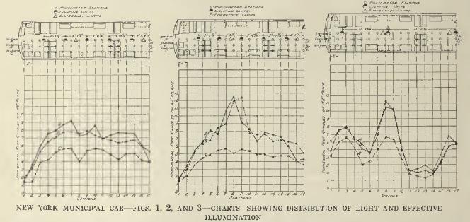
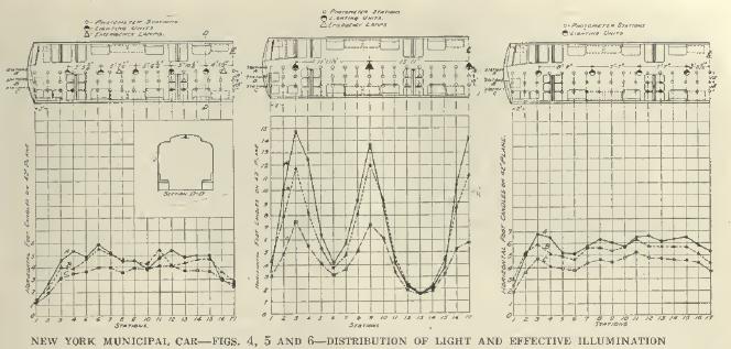

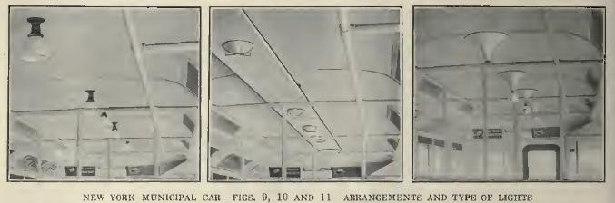
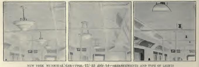


Brakes and Auxiliaries
Electric Railway Journal · Vol. 45, No. 19 · May 8, 1915 · pp 872-880.

Unusually Severe Conditions Are Set for the Air Brakes, in Which the Braking Pressure Is Varied According to the Load -- The Low-Voltage Coupler Greatly Simplifies Train Operation, Including Automatic Change of Marker and Tail-Lights -- Pneumatically Operated Doors with Spring Shock Absorbers, Automatic Speed Control, Buzzer Train Signals and Correct Posture Seating are Other Features.
In this article, which concludes the series on the multi-side-door car of the New York Municipal Railway Corporation, are described the braking equipment with its empty-and-load brake mechanism, the low voltage coupler, the interoperation of control, door, train light and train signal circuits, the automatic speed control, the heaters, signs and other auxiliaries. (For the preceding articles in this series, see Electric Railway Journal as follows: "Design," June 6, 1914; "Body," June 13, 1914; "Trucks, Brake Rigging and Draft Gear," Dec. 26, 1914; "Motors, Control, Conduit and Collectors," March 13, 1915, and "Lighting," March 27, 1915.)
Air Brakes
The air brakes are of Westinghouse automatic type AMUE with electropneumatic control and graduated release. Further, they embody the features of rapid recharge after each brake application and of auxiliary reservoir recharge without releasing the brakes. Emergency application of the brakes is obtained instantaneously and simultaneously on all of the cars of a train from the opening of the motorman's brake valve, the conductor's valve, or rapid reduction of brake-pipe pressure from any other cause. The brake-pipe pressure is 70 lb., and full service application gives 50 lb. brake-cylinder pressure with a fully loaded train. The electromagnet valves of the brake system are operated from the 32-volt storage battery on each car.
As noted in the article of Dec. 26, 1914, all wheels of each truck are fitted with clasp brakes, two shoes per wheel. With 50 lb. air pressure in the brake cylinder, the foundation and truck brake rigging, which is designed for a leverage ratio of 12:1, delivers a combined pressure on each pair of brakeshoes equal to 90 per cent of the weight on each trailer wheel and 110 per cent of the weight on each motor wheel.
The air brakes are to be operated under the local and express run conditions already detailed in the article of March 13, 1915. Broadly speaking, local trains are to make a schedule speed of 15 m.p.h. between terminals of local service and express trains are to make a schedule speed of 25 m.p.h. between terminals of express service. Some trains will operate in local service entirely and others in mixed local and express service. The trains will vary from two to eight cars, weighing 120,000 lb. each when fully loaded. The average lengths of stop for local and express service respectively will be twenty and thirty seconds. The average lay-over at terminals will be three minutes.
One important requirement is that the air brake shall be capable of making full emergency application after, or superimposed upon, ten possible applications with an average interval of 430 ft. when the train is descending inclines over the East River bridges.
On straight, level, clean and dry rail with trains of two to eight cars using cast-iron brakeshoes and with a brake-cylinder pressure of 50 lb. for service and the maximum obtainable for emergencies the following rates of retardation are specified.
Service Stop -- From an initial speed of 50 m.p.h. the average rate of retardation during a service stop must not be less than 2 m.p.h.p.s., provided the product of the efficiency of the brake rigging and the average coefficient of friction of the brakeshoes throughout the stop, expressed in percentage, is not less than 9.5 per cent. The period of retardation includes the time from the instant full service pressure is obtained in the brake cylinder to the instant of stop.
Emergency Stop -- From an initial speed of 50 m.p.h. the guaranteed average rate of retardation during an emergency stop must not be less than 3 m.p.h.p.s., provided the product of the efficiency of the brake rigging and the average coefficient of friction of the brakeshoes throughout the stop, expressed in percentages, is not less than 9.5 per cent. Here the period of retardation includes the period from the instant the brake-valve handle is moved to emergency position to the instant of stop.
Full emergency pressure is applied automatically whenever the brake-pipe pressure is reduced below a pre-determined point, whether through leakage or other causes. While possessing maximum sensitiveness to increases in brake-pipe pressure for the purpose of obtaining release, the brake is free from the tendency to "creep on" due to slight fluctuation in brake-pipe pressure. Any failure in service of the electric control of the brake system in service or emergency application results in the automatic application of the brakes, without further manipulation of the brake valve by the motorman.
Characteristics of Braking Apparatus
The D-2-F motor-driven compressor has a displacement capacity of 25 cu. ft. per minute at 600 volts. Its motor will operate the compressor at a minimum line voltage of 300 and a main reservoir pressure of 100 lb., and it will also operate satisfactorily on line voltages ranging from 300 minimum to 750 maximum. The compressor was subjected to a preliminary voltage test of 3000 a.c. for one minute, between windings and ground, while the commutator had to stand a voltage test of 200 a.c. between adjacent bars for one minute.
The compressor motor has ample capacity to operate for three hours continuously with 100-lb. air pressure in the main reservoir, on an average line voltage of 550, with a maximum temperature rise in the motor windings of 65 deg. Cent, above the surrounding atmosphere. Furthermore, the compressor must be capable of supplying the 1% cu. ft. of free air per car which the pneumatic door devices take at each station stop. It must also be capable of supplying the air for the chime air whistles.
One complete synchronizing system is furnished with each set of air-brake apparatus. This system is so designed that the first governor to cut in, after depletion of the main reservoir pressure, will close all compressor switches in the train simultaneously.
The compressor switch opens the motor circuit at a normal maximum of 750 volts, and is capable of opening, without injury, the compressor motor circuit during such current surges as may be caused by crossing gaps in the third-rail.
The governor cuts in and cuts out on a variation of 10 per cent of the main reservoir pressure, and its quick action is not influenced by a slow rate of depletion of the main reservoir pressure. Failure of any governor on the train to cut in does not affect the operation of the compressor switches on any of the cars in the train.
The emergency-valve (deadman's handle) feature in the motorman's cab has already been described in the article relating to motors and control. It is proper to add here that each car is equipped with the usual conductor's valve placed in the deck sill near the middle of the car.
Moreover the speed control equipment hereinafter described is so interconnected with the brakes that if a motorman disobeys a signal the brakes will apply automatically.
In addition to the usual gages, cocks, valves and other air-brake fittings, including American Type J automatic slack adjuster, there is installed the empty-and-load brake attachment described hereinafter.
All reservoirs are made of steel plate enameled inside to prevent corrosion and oxidation. They were tested by a hydraulic pressure of 200 lb. per square inch followed by an air pressure of 160 lb. per square inch.
All pipe used in connection with the air brakes is of iron lap-welded "Sherarduct." The fittings are of malleable iron, each tested under water with air pressure of 250 lb. per square inch. All pipe joints are made with shellac cut in alcohol, and the installation, when completed, was tested with a pressure of 125 lb. per square inch, at which pressure it had to be free from leakage. All unions are of rough brass with ground joints.
An individual spiral-shaft hand brake, especially designed by the railway, is available for contingencies. The ratio of this brake is 4:1, and it is operated by means of a ratchet handle. A drawing of the brake is presented in an accompanying illustration.
Empty-and-Load Brake Attachment
The object of the empty-and-load brake mechanism is to vary the braking power, as applied through the brakeshoes, in accordance with the variations in the live weight of the car. These variations are made when the doors are open; in other words, they occur only during the period of passenger interchange. The functions of this mechanism are carried out as follows:
When the doors of a car are opened, interlocks on the door-operating mechanism are in such position that an electropneumatic valve on the car body is energized from the storage battery. The action of this valve permits air to enter a vertical cylinder, which is mounted on the truck truss plank, and to push the piston of this cylinder outward and upward.
As the passenger load on the car increases, the movement of the elliptic springs on the truck tends to force this piston backward. This movement in turn actuates a vertical rack and pinion which are mounted on the body bolster. Any movement of the vertical rack is transmitted to a horizontal rack which in turn causes a connecting pullrod to vary the capacity of the auxiliary reservoir.
In this way the brake-cylinder pressure at full load is increased between 35 per cent to 40 per cent, with a 20-lb. reduction in the brake pipe. In case of an emergency application the braking power is increased practically 42 per cent. In short, the most efficient rate of retardation is maintained for any degree of loading.
The empty-and-load brake mechanism is also tied in with the selective acceleration feature of the multiple-unit control. This is accomplished by means of an extra winding on the limit switch whose modification of current input to the motors is controlled from a switch operated in connection with the empty-and-load brake mechanism.
A full appreciation of the great value of this improvement is obtained only when one considers the effect of a 40 per cent increase in the total weight, by means of the live load, upon the stopping distance of multiple unit trains as heretofore braked. The weight of the empty train determines the maximum braking power that can then be applied to it, and under the old conditions an increase of 40 per cent in weight meant lengthening all the stopping distances obtainable with the empty train by about 40 per cent when the same train was loaded. With the empty-and-load brake attachment, all trains can be stopped in the same minimum distances, irrespective of loading. The acceleration also is maintained at a uniform maximum for any given grade condition, irrespective of loading.
These important factors, together with the shorter spacing of block signals involved, permit a remarkable increase in train capacity on any rapid transit railway.
Automatic Car, Air and Electric Couplers and Junction Boxes
In place of the usual loose-fitting car couplers, double sets of air hose and train-line receptacles with removable jumper connections, the Westinghouse combined car, air and electric coupler was adopted for the following reasons:
1. Less time needed to couple and uncouple the cars.
2. Less hazard in coupling cars.
3. Freedom from possible accidents due to dragging jumpers.
4. Superior contact for train-line connections.
5. Saving in the cost of coupling cars.
6. Simpler installation, because one-half of the trainline terminals are eliminated.
7. No extra provision for housing in the cars or at the terminal for detached jumpers.
8. Simple and safe automatic operation of auxiliary contacts at the end of the train for marker and signal purposes.
9. Greater facility in cutting the train line to locate trouble, thus minimizing possible delays.
10. Material reduction in cost of maintenance.
11. Because there is no wear between car coupler faces, this expense in maintenance is eliminated.
Perhaps the most important feature of the automatic electric coupler is that only one operation is required, namely, that of throwing the coupling valve in the motorman's cab. On the contrary, with the preceding jumper system fully sixteen operations were necessary and only a few of this large number were due to safety gates, chains and other non-train-line devices.
When the motorman throws the coupling valve the main control, the speed control, the air brakes, the signal lights (including the extinguishing of marker and tail-lights between cars), the buzzers, and all other train-line auxiliary circuits are in normal service.
All of the foregoing advantages are made practicable by the fundamental fact that the car coupler, to which the air and electric connections are attached, is of the absolutely tight-lock type. When two of these coupler heads have been united the two parts become as one piece, so that when in service a thin coating of brake-shoe dust extends across the two, there is no crack to indicate the line of juncture.
One junction box near each end of the car and one at the center of the control box with terminal studs are provided to form the train-line connection between the automatic couplers, the master controller, the control box and the brake and auxiliary apparatus.
At the end junction boxes are outlets for all train-line wires, including the main control, speed control, brake, marker and tail-light and signal circuits. At the central junction box separate outlets are provided for the control circuits, the brake circuits and the battery supply connections. Each terminal clip is marked with the number of the wire to which it is to be connected, and the terminal board is usually marked with the train-line numbers on each stud.
Door Operation
As stated in the earlier articles the New York Municipal car has three pairs of sliding doors on each side and a single door at each end. One operator stationed on either side of the car midway between the two middle doors, is able, by means of the push-button board illustrated, to operate all doors on the side nearer to him, and, also to operate both end doors from the same position. He can also operate the doors on the opposite side of the car by manipulating the buttons on the opposite panel. In all, each car has fourteen door engines and eight electropneumatic valves.
All engine valves are equipped with an attachment for opening or closing their respective doors by hand from the inside of the car. The respective valves are also equipped with an attachment for opening and closing from the outside the two end doors and each pair of middle doors, by means of properly-protected push buttons outside the car.
The doors will operate at main reservoir pressures of 80 lb. minimum to 100 lb. maximum. It was specified that all door mechanism must be capable of making 300,000 strokes in service between applications of lubricant. The wear of operating parts during these periods must not cause valves or piston packing to leak. The variation in the time of door opening and closing between applications of lubricant must not be more than 10 per cent with an air pressure of 100 lb. per square inch in the main reservoir with atmospheric temperature ranging from zero to 90 deg. Fahr.
The door-operating mechanism, which was built by the Consolidated Car Heating Company, embodies some valuable improvements to meet the New York Municipal requirements. Probably the most important of these requirements was that relating to the time of the door-operating cycle.
The railway company felt that in a service with the short station stops specified a rapid yet absolutely safe door mechanism was essential. It therefore specified that all door engines should be capable of opening the doors in one and one-half seconds from the time that the operator pushes the button. This speed, however, is too high for door closing; consequently the time allowed for closing is two seconds. Thus by adding one-half second to the period of closing the entering passenger is not subjected to severe shock should he come in contact with the door. Still further to insure non-injurious closing a spring has been interposed between the piston and the door whereby the door is operated with a cushioning effect in addition to employing the usual rubber cushion at the edge of the door.
On the whole, this door-operating mechanism is a notable improvement over earlier designs.
At one of each pair of side doors is a folding seat which is so connected to a three-way cock in the air feed to the door engine, that when the seat is in use the respective door engine is cut out of action. Thus it is impossible to open the door until the seat is folded up to clear the door.
Buzzer and Door-Signal Circuits -- Emergency Lighting
A buzzer-signal circuit replaces the slow and obstructive bell cord. The buzzer push buttons are mounted just above and on the same panel as the door-control buttons. This signal circuit is so wired that the guard who pushes his buzzer button transmits the signal no further than to the buzzers in the forward cab of his own car and the rear cab of the car ahead. In this manner the signal is transmitted ahead from car to car. The wiring is so arranged that it is impossible to skip a car. This circuit, which is fed from the storage battery, is closed by means of interlocks mounted in the door pockets, the interlocks being operated by means of attachments on the doors themselves.
The motorman depends upon the buzzer circuit only at such times as the light signal in the operating master controller is out of order. These lights burn only when all the doors in the train are closed. The light signal consists of two lamps of 6-volt automobile type, and as but one is in use at a time the possibility of total failure is very remote. The second lamp goes automatically into circuit when the first one burns out.
The circuit for the signal lights is so connected through the reverse drum of the master controller that the signal is displayed only in that master controller which is in the operating position, thereby avoiding waste of energy and unnecessary indications.
Between each pair of doors is mounted one 10-watt, 34-volt frosted-bulb tungsten lamp. The positive circuit of these lamps is connected to one blade of a double-pole, single-throw lighting switch. The negative side is connected to contacts on the voltage relay which is always energized when power is on the line. In the energized position the relay disconnects the negative side of the emergency lighting circuit. Therefore, when normal lighting is in service the main lighting switch will be in the closed position. On any failure of the traction circuit the voltage relay drops and the negative side of the emergency lighting circuit is completed to the storage battery.
Marker and Tail-Lights
The marker and tail-lights are interconnected with the control circuit in such a way that when the motorman changes train ends his tail-lights automatically change from white to red as soon as he throws the reverse handle to the center position; vice versa, the red lights turn to white on throwing the handle to the operating position. Should the train be broken up en route in any way, the tail-lights will go red at the point of breaking. This is accomplished by combinations in the automatic coupler and control as previously stated.
The two marker lights provided in each hood of the car have stationary white semaphore lenses. Colored disks of the Railway Signal Association standard colors are arranged inside of the hood, connected so that any desired color may be placed between the lamps and lens. The marker lights on each side of the hood are operated independently.
The tail-lights consist of one white and one ruby 4-in. diameter 2-3/4-in. focal length semaphore lens as per the Railway Signal Association standard colors in each set. They are lighted from the storage battery by incandescent lamps placed behind each lens. The lenses are held permanently in place by pressed steel retainers riveted to or pressed in the end sheet with removable retainer rings.
Heater Circuits -- Signs
The heating equipment per car totals 21 kw capacity divided among thirty heaters with two coils per heater. All coils are interchangeable. The three-point system is used, twenty coils being in series on each point. Piping and wiring connections for thermostatic control have been installed in view of the possible later use of thermostats.
Destination signs are displayed in every car in the windows alongside the central pair of side doors. These signs are of double curtain type, as furnished by the Electric Service Supplies Company.
Correct Posture Seating
In concluding the description of this car it is fitting to add some details on the radically different type of rattan car seating. From the first the engineers of of the company had planned a seat which would not only be of the transverse type where practicable but which would also permit a more comfortable bodily position than previous designs. With the assistance of the American Posture League, an organization of experts on hygiene and anatomy, the design was improved still further by certain modifications in the angularity of the back and in the height of the seat cushion. In the seat as finally adopted, the distance from the highest point of the unoccupied seat cushion to the floor is 17-5/8 in. The league's ideal figure of 17-1/4 in. is approximated when the seat is depressed by the weight of the passenger. This height, as compared with the usual one of 18 in., permits good footing for all but very small children.
A still more important feature is that the back is so shaped that the rattan section begins at a height of about 5 in. above an inwardly curved metal section which forms the base. As shown in the several accompanying halftones and drawings, this formation of the back allows the lower part to fit the natural curve of the human spine, while the upper part gives a proper support for the back. The result is to place the passenger in the most restful position. Since his body is properly balanced he is also less likely to be disturbed by any sudden lurching of the car. The league has affixed its approval plate to the seats in the New York Municipal car, and will gladly co-operate with other railways to achieve scientific seat design. The seats are of the Hale & Kilburn Company's manufacture.
Speed-Control Signal System
In lieu of the usual signal system employing fixed signals and automatic stop devices placed at certain intervals along the track, each car is equipped with a cab signal system so designed as to give the motorman necessary information as to when to apply the brakes, when to resume normal speed, the permissible speed, the available braking distance, and such other information as is necessary properly to control the train. In addition to the signals, each car will be equipped with a speed-control system which automatically applies the brakes if the motorman fails to obey the cab-signal indications. Also, the system is arranged so as to enforce obedience to fixed interlocking signals by automatically applying the emergency brakes if a train should attempt to pass such signals in the stop position.
Cab signals, one of which is shown in an accompanying halftone, are located in both ends of each motor car and are so arranged that their indications are visible only in the cab from which the train is being operated and controlled. Cab-signal indications are given by two lights as follows : A green light indicating "proceed" when the next two blocks ahead are clear; and a yellow light indicating "caution" when the next block ahead is clear and the second block ahead is occupied or is governed by an interlocked signal indicating "stop," or when the train is on a down grade or curve or when it has some other fixed hazard.
The audible signal, provided in each motorman's cab, is so designed and interconnected with the speed-control mechanism, that it sounds sufficiently long in advance of the automatic speed-control application of the brakes to permit the motorman to control his train so as to avoid the automatic application of the brakes. An indication is given in each motorman's cab to show the maximum allowable speed and the distance within which, succeeding the giving of a caution signal, the speed of the train must be reduced to the prescribed minimum to avoid the automatic application of the brakes.
The speed-control apparatus is so arranged that when a train runs into an unsignaled section of track a distinctive indication is displayed in the motorman's cab, and the cab signals and speed-control equipment are automatically put out of service and automatically return to service when the train again enters the signaled section of track.
The speed-control equipment does not interfere with the operation of the train so long as the motorman runs his train according to the indications of the cab signal, but, if the motorman fails to obey the "caution" signal, the speed-control apparatus enforces obedience by automatically applying the brakes, but only when and if the speed of the train, at any point, exceeds that prescribed by the predetermined braking curve.
When a train, running at a speed not exceeding the prescribed minimum, approaches a clear block, its speed-control apparatus is, prior to entering the block, automatically reset in such a manner as to permit the train to accelerate. If a clear block is succeeded by an occupied block, the train is permitted to accelerate, slowing down should the speed thus acquired exceed that established by the predetermined braking curve. If a clear block is succeeded by another clear block, the train is permitted to attain normal speed.
Suitable means are provided whereby, in the event of its failure, the speed-control mechanism on any car can be safely cut out of service in such manner as not to interfere with the operation of the speed-control apparatus on the remaining cars of the train.
The speed-control and cab-signal equipment is actuated by means of ramps located adjacent to the tracks at such points as provide the required track capacity and facility of operation.
The cab signals are block signals and indicate the condition of the blocks in advance; at crossings, junctions, terminals, etc., fixed signals, which are of the light type, are used to indicate the route set up. The indications of interlocking signals are given by one light as follows:
| Indication | Aspect |
| Proceed on same track | One green light |
| Proceed on diverging light | One yellow light |
| Stop | One red light |
The speed-control apparatus on each car is arranged so as to enforce obedience to the interlocking home signals by automatically applying the emergency brakes if a train should attempt to pass such signals in the stop position.
An accompanying drawing shows speed and braking curves for a typical block, which in this case is 1200 ft. in length. The emergency braking curve A represents the distance within which, succeeding an emergency application, a train is brought to stop before reaching the end of the block. The design of the speed control system enforces obedience to this curve by automatically applying the brakes in case the speed of the train, at any point, exceeds that indicated by this curve. The automatic application of the brakes takes place at varying distances from the end of the block, depending upon the speed, this being one of the essential features of the system. The usual system employs automatic stops with an overlap, the length of which is always based on maximum speed, and failure to obey a stop indication would cause an emergency application at the same point, regardless of speed. This requires that trains must be spaced apart a distance equal to the length of the overlap, which is usually a full block or more, whereas in the speed-control system trains can close up, provided always that the speed has been reduced to a point within the braking curve. In the speed-control system greater facility is provided, owing to the fact that trains can close up instead of being spaced a full block apart.
Curve B is the normal braking curve and represents the retardation which results from a service application of the brakes. Curve C is the audible-signal curve. The audible signal is given sufficiently in advance of the service-braking curve so as to avoid an emergency application if the motorman obeys the audible indication and applies the brakes. This curve is an important factor in facilitating traffic in the case of a train entering the block at less than normal speed as follows:
If a train enters an unoccupied block at low speed it can accelerate, as shown by curve D, until the curve intersects audible-signal curve C, at which point, if the brakes are promptly applied, curve D merges into curve B and an emergency stop is avoided.
Curve E shows a train proceeding at less than maximum speed, in which case the audible signal is given at the intersection of the speed line and curve C. If the brakes are promptly applied an emergency stop is avoided as in the preceding case.
A train can enter an occupied block, as shown by curve F, but cannot exceed the prescribed minimum speed. Curve G is a continuation of curve D and shows the acceleration attained if the block in advance is clear.
If two blocks in advance are clear, in which case the cab signal would show a green light, a train entering the block shown in the diagram mentioned could proceed at normal speed without interference from the speed-control apparatus. If the block in advance was clear but the second block in advance was occupied, the cab signal would show a yellow or "caution" indication and, if the motorman does not apply the brakes, an automatic emergency application of the brakes occurs, bringing the train to a stop before reaching the end of the block.
Operation of Speed-Control System
The diagram on page 880 shows the principles of the signal system. At one end of the track circuit a transformer, T, supplies electric energy which flows through the track circuit and, when the block is unoccupied, energizes track relay R, and its front contact closes a circuit from battery, B, or some other source of electric energy. Hence when a car is at a ramp, as in this case, current flows through the ramp, through the contact shoe S, and then through the car relay C, causing its armature to pick up, and back to the common return by way of the car axle and one of the track rails. In this condition current from the battery D flows through and energizes the green light G of the cab signal, which gives the "proceed" indication. Energy from battery D also flows through and energizes magnet E.
After the train has passed an energized ramp a retaining circuit is established by way of contact A, so that current from the battery D energizes the car relay C and the green light or "proceed" signal continues until the next ramp is reached.
If the track circuit was occupied, track relay R would be de-energized, and as a result the ramp, also the car relay C and the magnet E would be de-energized. In this condition current from the battery D flows through and energizes the yellow light Y of the cab signal to give the "caution" indication.
Magnet E controls the speed-control apparatus, which operates in the following manner: The rotating motion of the car wheels is transmitted by means of the bevel gears shown in the drawing, to shaft J, on which is mounted a centrifugal device or governor which is so arranged and connected that, as the speed increases, the arms K and L are moved to the left. The worm H is driven through the medium of shaft J and is held out of engagement with the worm sector N by the attraction of the magnet E. When the magnet E is de-energized, the worm H engages with the worm sector N, causing the cam M to move forward against the action of gravity. The shape, speed and general arrangement of cam M are such that if the speed of the train is not reduced, succeeding the giving of a caution indication, the surface of cam M, coming in contact with the lever L, opens the contact Q and the audible signal warns the motorman to apply the brakes.
If the motorman promptly applies the brakes arm L moves to the right, away from the cam M, thus preventing the opening of the contact U and the consequent application of the brakes. If, however, the motorman fails to obey the audible signal, the contact U opens and an emergency application of the brakes occur.
Upon reaching the next energized ramp the magnet E is energized, which disengages the worm H and the sector N, and cam M is restored to its normal position by the action of gravity, thus restoring the speed-control system to the normal condition which allows the train to accelerate. If the next ramp is de-energized, the train may proceed through the block only at minimum speed, which minimum speed is determined by the maximum radius of the cam.
The selector, shown at the left of the drawing below, in its proper position on the car, sets up the various "block combinations" and indicates the same to the motorman. Combinations are set up by selector ramps, in the center of the track, which lift up one or more of the tappets shown on the lower part of the selector. When lifted by the selector ramps the tappets latch up and are so held until a new combination is set up, at which time the former combination is knocked down by the center tappet. Complete information is given in the cab as to the point at which speed reduction must take place, in order that a lower speed combination may not be set up prematurely and apply the brakes. For example, if the change is to be from a combination of 50 m.p.h. and 1600 ft. braking distance to a combination of 20 m.p.h. and 400 ft. braking distance, first, a "caution" signal is given to the motorman so as to allow him to reduce speed, and, after the speed is properly reduced, the new combination becomes effective, and a "proceed" signal is given, provided that conditions in advance are proper. If the motorman fails to obey the indications shown in the cab, an automatic application of the brakes occurs.
The speed-control mechanism in proper position on the car is also shown in the cut. The operation of this mechanism is described in connection with the simplified diagram. The drawing of the speed-control mechanism shows the contact shoe in the proper position on the car, also the ramp. The contact shoe is of the lifting rotary type, in which the disk contacts with a ramp. The disk, which is inexpensive and easily replaced, travels over the ramp with a scrubbing movement which maintains a smooth contacting surface. The lifting of the contact shoe opens a circuit which de-energizes the car relay, if current is not flowing through the ramp, as described in connection with the simplified diagram. The cab-signal and speed-control system requires comparatively a small amount of simple, substantial and efficient apparatus, and affords maximum traffic capacity consistent with safety. The system is being installed by the General Railway Signal Company, Rochester, N. Y., under the Simmen patents for speed control.
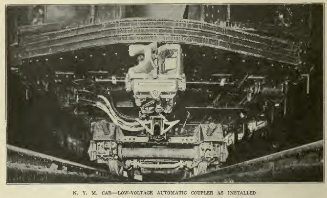 NEW YORK MUNICIPAL CAR -- LOW-VOLTAGE AUTOMATIC COUPLER AS INSTALLED. |
 NEW YORK MUNICIPAL CAR--VIEW OF PANEL BOARD FOR AUXILIARY CIRCUITS. |
 NEW YORK MUNICIPAL CAR -- DETAILS OF HAND BRAKE. |
 NEW YORK MUNICIPAL CAR -- PUSH-BUTTON BOARD FOR DOOR CONTROL; HAND BRAKE BELOW. |
 NEW YORK MUNICIPAL CAR -- DOOR-CONTROL MECHANISM UNDER SEAT. |
 NEW YORK MUNICIPAL CAR -- THE HUMAN BODY AND THE CAR SEAT. Fig. 1 -- The natural curve of the backbone. The proper points where a seat should give support are at the lower part of the shoulder (a) and the small of the back (b). Fig. 2 -- The prevailing style of street car and Pullman car seat, which, being padded at the wrong place, pushes the pelvis out and affords no support for the back. Fig. 3 -- The new "correct posture" seat which allows an opening for the lowest part of the back and is made to fit the natural curves of the human spine. |
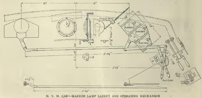 NEW YORK MUNICIPAL CAR -- MARKER LAMP LAYOUT AND OPERATING MECHANISM. |
 NEW YORK MUNICIPAL CAR -- VIEWS SHOWING CORRECT POSTURE SEATING OF DIFFERENT TYPES. |
 NEW YORK MUNICIPAL CAR -- CORRECT POSTURE LONGITUDINAL AND CROSS-SEATS. |
 NEW YORK MUNICIPAL CAR -- VIEW OF CAB SIGNAL AS INSTALLED. |
 NEW YORK MUNICIPAL CAR -- DETAILED DIMENSIONS OF CORRECT POSTURE CROSS-SEAT. |
 NEW YORK MUNICIPAL CAR -- SPEED-CONTROL SELECTOR; CONTACT SHOE AND SPEED-CONTROL MECHANISM. |
 NEW YORK MUNICIPAL CAR -- TYPICAL SPEED AND BRAKING CURVES FOR SPEED CONTROL. |
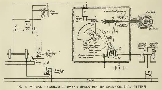 NEW YORK MUNICIPAL CAR -- DIAGRAM SHOWING OPERATION OF SPEED-CONTROL SYSTEM. |
New York Municipal Car Improvements
Electric Railway Journal · Vol. 57, No. 24 · June 11, 1921 · pp 1087-1080.
Since the Introduction of the Large Multi-Side-Door Cars on the Lines of the New York Municipal Railway Various Additions and Refinements Have Been Made to Provide Increased Comfort and Safety for Passengers.
 New York Municipal Car - Low monitor type roof construction with deck-sash ventilators, ventilating fans and rearranged lighting. |
 New York Municipal Car - Destination sign with large letters and number on side of car. |
When the Brooklyn Rapid Transit System offered to operate a part of the vast subway and elevated network as suggested by the city of New York in 1911 the design of a car most desirable was one of the vast problems presented to the engineers of this company for solution. When the various details of design were finally settled the most noteworthy characteristics of this car in which it differed from other designs were its large size, its unique seating arrangement and its multi-side-door construction. The value of these new features embodied in the design has now been demonstrated by more than five years of service under the most severe traffic conditions that can be found in any city. At present 900 of these cars are in service or on order and in the fundamental considerations the last cars, namely, the 2,800 series, are identical with the first ordered. Quite a number of refinements and improvements have been added, but the changes which were made in construction were very few.
The essential characteristics of the design, construction and equipment of these cars were very completely covered in a series of articles published in the issues of the Electric Railway Journal for June 6, 1914; June 13, 1914; Dec. 26, 1914; March 13, 1915; March 27, 1915, and May 8, 1915. The purpose of the present article is to describe some of the improvements and changes incorporated in the last 100 cars ordered and include additions made since this series of articles was published.
Monitor Type Roof for Ventilation
The form of roof used with the 2,800s is of a low monitor type with twenty deck-sash ventilators on each side of the car. This construction provides a clerestory 4 ft. 11 in. wide inside by 12-1/2 in. deep. The deck-sash ventilators are arranged in four groups, so that those in a quarter of the car can be operated separately from a lever near the center of the car. The ventilators swing horizontally and have an opening of 25 in. by 4-1/2 in. This type of roof construction lends itself particularly well to the ventilation system using five ceiling fans in each car.
The five ceiling fans are arranged with one opposite the center pair of doors and the others at about equal distances along the center of the headlining. The five fans of each car are connected in series across the line, so that each fan is wound for 115 volts. The fan motor frame is designed for direct attachment to the car ceiling and a metal canopy incloses the top part of the motor.
With the use of the ceiling fans the arrangement of lights consists of fourteen side lights, seven on either side, installed just at the edge of the clerestory, and six center lights, two of which are end lights. There is thus a total of twenty 56-watt lamps with shades per car. The fundamental principle of the seating arrangement adopted for the New York Municipal cars was to obtain maximum seating capacity during hours of normal traffic and maximum standing room plus a reasonable proportion of seating capacity during the rush hours. In order to facilitate movement to and from the door openings the space opposite each active doorway was kept free, except for vertical stanchions installed for the accommodation of standing passengers. Study of the conditions that existed with the cars loaded to their maximum capacity indicated that a few hand straps on either side of the door openings provide comfort for the standing passengers, and accordingly twenty-eight hand straps, fourteen on either side of the car, have been installed. These are grouped with two hand straps on either side of the end side doors and three hand straps on either side of the center pair of side doors. These are of the Henry type, all metal with white enameled hand grips, and arranged to be held back close to the side of the car by spring pressure when not in use.
Improvement in Folding Seats
In order to increase the seating capacity during hours of normal traffic, hinged folding seats are used on either side of the door openings. In their raised position these folding seats serve as ends for the longitudinal seats and a grab handle along the front edge enables standing passengers to get a firm hold. These folding seats are held in their raised position by a lock catch which can be released only by the aid of the key used for the end doors and the operator's push-button box. With the seats in their "down" position a prop swings out from the under side and rests on the floor. This seat prop is made of a pipe framework with two legs which have rubber cushions at the points where they rest on the floor. All parts are rounded so that no sharp corners or projections are presented, which might prove injurious to passengers or their clothing, and as this framework is mounted so that it extends out from the side of the seat it also serves as a grab handle for standing passengers, with ample space for their fingers to provide against accident. A center leg of this framework is attached to a lever which is connected to the door engine underneath the stationary seat at this point. The lowering of the folding seat cuts off the air from the door engine, so as to insure that the door behind the seat cannot be operated with the seat in its down position.
It is the practice of the New York Municipal Railway to operate trains with the end doors of the several cars closed, and the seating arrangement provides a small seat just to the left of each end door with hinges, so that it can be raised but cannot be removed.
Two cross seats are located just to the rear of the motorman's cab. This is the only position in the car where two cross seats come one behind the other. To provide additional leg room for passengers in the rear seat, the back part of the front seat has been constructed with a cut-out portion, which comes just below the back seat cushion. By this ingenious arrangement, an additional 3 in. of leg room is provided for passengers without change in the other parts of the seat construction.
No Danger of Interference with Motorman
To provide maximum privacy for the motorman the door of the cab has been provided with a steel panel in the top portion and a small length of wire-ribbed glass in the center portion. The bottom of the door is also provided with a dust guard, as it is found that with the car in motion a current of air from the end door blows in through the motorman's cab, particularly when the window is raised. Thus dust and other particles are blown under the bottom of the door. The steel panel in the rear of the motorman's cab is utilized for an advertising sign rack.
Several window positions have steel panels. One of these is just to the left of the end door and others are provided just to the side of the end side doors. The use of steel panels reduces the maintenance cost for broken glass considerably and also provides increased revenue from their availability as advertising sign racks.
Drop sash have been provided in the end doors which are arranged for the dropping of the top part of the sash, the window being made in two parts. This gives increased ventilation and a circulation of air through the entire train.
In one of the accompanying illustrations showing exteriors of the cars the paneling of the small window to the left of the end-side doors can be seen. In these cars the car number has been placed on the side of the car over this window. It was found that this is preferable to numbered glass which when broken causes considerable delay in returning the car to service, as a new glass has to be numbered and the paint thoroughly dried before it can be installed. The routing and destination sign is located in the second window to the right of the center side doors. This location provides for use of signs with large letters which can be distinctly and easily read, and also gives more space for the sign proper, as the number of destinations and routes are increasing considerably due to the addition and operation of new lines.
In the illustration of the outside end of the car the pantograph safety gates are shown. A wide shoe now used insures proper contact even on sharp curves. Another view, taken between two cars, shows the threshold plates at the end doors. In the new design the outside ends have been cut off so that they extend but a few inches outside of the end doors.
Electric Trip Switches Added
In the views showing truck construction and equipment electric trip switches are shown at the left end of the truck. Two of these are installed per car on diagonally opposite corners. This truck mechanism for the trip switches consists of a lever which extends down toward the rail and engages the track trip. This lever is self-centering by heavy springs and acts through a gear and pinion to operate a contact device and open the circuit whenever it is operated. The opening of this circuit de-energizes the holding coil of an electro-pneumatic valve installed in the small cabinet over the push-button switches on the inside of the car. This electro-pneumatic valve operates a dead man's valve which opens the brake pipe and causes an emergency application of the brakes. As soon as the track trip has been passed, the truck trip switch returns automatically to its central position, closing the circuit at that point. However, the circuit still remains open, due to the dropping of the electro-pneumatic valve. A reset circuit is used for restoring the valve to its normal position, with a reset switch in each motorman's cab. There is also a pneumatic switch in this circuit, which is connected directly to the brake pipe. This closes whenever the brake pipe pressure has been reduced to 5 lb. or less. The electro-pnuematic valve can then be reset without the motorman moving from his cab, but as the brake pipe pressure must be reduced to 5 lb. before this circuit is closed ample time is given to insure that the train comes to a stop before the normal condition can again be re-established.
The cast-steel contact shoe is also shown in the second illustration, and the shoe-fuse-box cover. The cover is of wood, reinforced with wide steel bands having spring mounting.
The journal boxes provide substantial support for the shoe beams and heavy brake-shoe release springs assure prompt release from the wheels. Following the general practice in this design of providing safety straps for all brake-rigging parts, additional safety straps have been added under the truck slack adjusters. A cross-connection has also been added between the brake-shoe hangers at the end of the truck. This gives a rigid construction and prevents brake shoes from developing false flanges or wearing out of true.
All doors of a car are controlled from push-button boxes forming a part of switchboard panels located on either side of the car between the center pair of doors. The push buttons are arranged in three rows, those in the center row being for opening the doors. To energize any of the push buttons it is necessary for the operator to insert a key in the key switch at the upper left-hand corner of the box and to turn this to close the circuit to the button. As an extra safeguard on the opening buttons, a cast-bronze guard is installed over them. With this in place there is no danger of false operations with the cars in motion should the operator forget to remove his key from the key switch.
The lighting, heater and compressor switches are located at the top of the panel board. An ingenious method of preventing the operator from hanging on to the steel door of the panel board or other grounded metallic parts while he is throwing these switches involves the use of an insulated safety cover. This cover is hinged from a point just above the top of the switches, and in its normal position extends down so as to cover the switches and the fuses completely. In order to throw a switch it is necessary for the operator to raise this insulated panel, and the most natural method of doing this is to hold it in its raised position with the left hand while the switches are being thrown with the right hand. The operator must maintain his hold on this insulating panel, which insures his being insulated from ground without danger of receiving a shock should he inadvertently touch any live part. This insulated panel also forms a very conspicuous place for posting information regarding the various fuses and switches. All fuses and switches are given numbers on the panel board and the instructions tell what circuits they are used in, so that should trouble occur in service the operator does not need to test several circuits to find the trouble, but can locate it immediately by referring to the instructions.
Convenient Method of Operating Light Switch
Another ingenious and trouble-saving device is the key-lighting switch, located at the right-hand center part of the panel. As these cars operate in the open as well as in tunnels, it is necessary to turn the lights on and off during each trip. With the usual type of lighting switch this would require the opening of the panel board door each time it was necessary to throw this switch. This requirement has been done away with by the use of a key switch in the lighting circuit which can be operated by the insertion and turning of a key without opening the panel board door. The keyhole for this switch is made with a large funnel-shaped guard, so that the operator can readily find the keyhole even should he neglect to turn the light on in the car until after it enters the tunnel.
This panel board also contains the switch for operating the ventilating fans. This is a safety switch located just underneath the safety lighting switch. All exposed parts of this switch are insulated, so that the operator cannot come in contact with any live parts.
The hand-brake handle folds back against the side of the car just underneath the small switchboard panel and is held in position by a safety catch. The steel side panel has been cut out just at the handle to provide additional space for the inserting of the hand for operating the hand brake.
The storage batteries of the car are charged from the line as well as through the compressor circuit. A battery-charging relay operates to connect the car batteries to line through a resistance whenever the pressure drops as low as 26 volts. With the batteries connected for charging directly from the line a 2-amp. charging current is received. The normal voltage for these batteries is thirty-four, and whenever this voltage is reached the battery-charging relay automatically cuts out. In normal operation the batteries are charged through the compressor circuit.
Electro-pneumatic line switches, Westinghouse type 267-E-9, are used on these cars. These are found desirable on account of the large number of times that the main operating circuit is opened and closed while going over gaps in the third rail.
Improvements in the electro-pneumatic brakes used provide for a quick application of the brakes throughout a train at all times whether they are applied pneumatically or with the electric features cut out. An indicating pilot lamp is connected so as to show whenever the brakes on a car are cut out. This pilot lamp is located inside the car just to the right of one set of the end side doors, and its conspicuous location insures that cars are not operated in service with brakes cut out unless it is essential due to trouble on that particular car. The motorman is then advised of the condition, so that safe operation is assured.
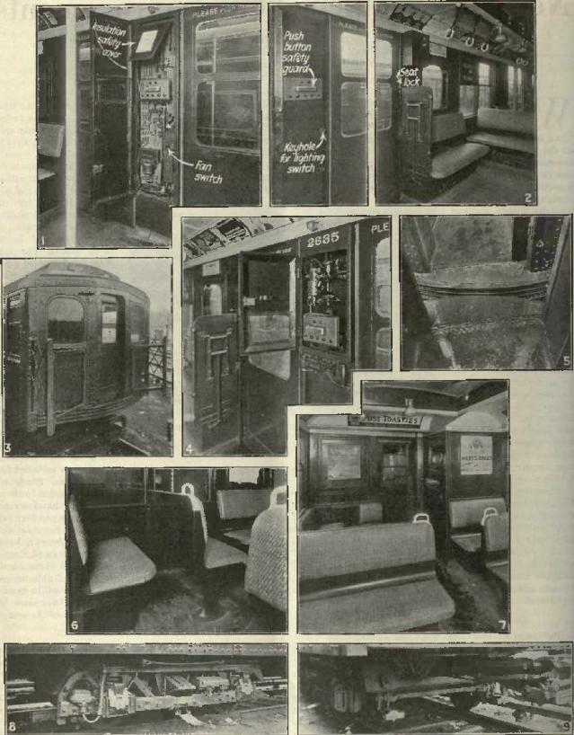
Sources
Electric Railway Journal, McGraw Hill Company, Digitized by Microsoft, Americana Collection, archive.org.