Frankford Elevated News (1915-1927)
Frankford Elevated News (1915-1927)
Electric Railway Journal · Various Issues, 1915-1927

READY FOR SERVICE. Some of the 50 large new all-steel cars going into operation on the Frankford Elevated Railway, Philadelphia... [Westinghouse advertisement, April 15, 1922. See below.]
A collection of short news articles about Philadelphia's Frankford Elevated, from various issues of Electric Railway Journal.
June 26, 1915.
The Philadelphia Transit Loan. -- The surveys committee of Councils of Philadelphia has reported favorably a bill directing A. Merritt Taylor, director of city transit, to contract for the relocations and the rebuilding of certain sewers in Philadelphia in the interest of the proposed Broad Street subway and Frankford elevated line. The report of the sewer bill was followed by the passing of a resolution providing for additional stated meetings of both chambers of Councils on June 23 and 30 to act on the bills appropriating the money and authorizing contracts to be let for an immediate start on the work of transit improvement.
July 3, 1915.
The Philadelphia Transit Ordinance. -- By unanimous vote the Common Council of Philadelphia, Pa., has passed the ordinance authorizing the $6,000,000 transit loan. The finance committee's plan is to have the loan ordinance transmitted to the Mayor as soon as it is concurred in by Select Council. Immediately upon being advised that the ordinance has been approved by Mayor Blankenburg, the finance committee will report the appropriation ordinance, which will be passed by both chambers. The committee proposes to allot $3,000,000 for preliminary work on the Broad Street subway and $3,000,000 to the Frankford Elevated line.
July 10, 1915.
PHILADELPHIA TRANSIT LOAN APPROVED. The Councils of Philadelphia, Pa., on July 1 by unanimous vote passed ordinances appropriating the $6,000,000 transit loan to the Department of City Transit and authorizing Director of City Transit A. Merritt Taylor to let contracts and start work immediately on the Broad Street subway and the Frankford elevated. The ordinances allotted $3,000,000 of the loan for each of these projects. Actual construction work on both projects will be started on Sept. 13. Mr. Taylor says that if there is no delay in making the loans available, the entire Broad Street subway can be completed in thirty-two months and the Frankford elevated road within two years. [...]
Advertisements were scheduled to appear in the papers on July 8, inviting bids for the construction of the foundations for the Frankford elevated line, between Callowhill Street on the south and Unity Street on the north. Bids for this work will be opened on Aug. 16. The specifications call for actual construction to be commenced on Sept. 13, and for the contract to be completed within eight months. Advertisements will appear in the papers on July 26 inviting bids for the construction and erection of the steel work for the section of the Frankford elevated line, extending from Callowhill Street on the south to Unity Street on the north. Bids for this work will be opened on Aug. 23. The specifications call for the erection of the steel work to be commenced on Dec. 1, 1915, and for the contract to be completed within one year.
July 31, 1915.
Philadelphia's application for a certificate of public convenience, the next step toward building the Broad Street subway and the Frankford elevated, was argued on July 26 in Harrisburg before the Pennsylvania Public Service Commission. Appearing in opposition to granting the certificate were E. A. Ballard, chief counsel Philadelphia Rapid Transit Company; Ruby R. Vale, counsel for D. E. Dallam, whose suit for an injunction was described in the Electric Railway Journal of July 24; and Charles L. Fluck, of the Northwest Business Men's Association. City Solicitor Ryan was present on behalf of the municipality, and A. Merritt Taylor, Director of City Transit, was the sole witness heard.
September 16, 1916.
Philadelphia, Pa. -- Following the announcement by Mayor Smith that a $10,000,000 portion of the new city loan is to be floated by a bond issue Nov. 1, Director Twining, of the department of city transit, announced on Sept. 7 that estimates for work on three sections of the huge subway loop would be called for in a few months and that the contracts would be awarded in January. It is estimated that about one-quarter of this $10,000,000 will be devoted to transit and port improvement purposes. According to Director Twining, the major portion of the 1917 construction work will have to do with the subway loop and the Frankford elevated. The preliminary plans for this work will be passed upon by the Public Service Commission engineers within a week or so. After this the department will immediately proceed with the plans in detail. Director Twining, speaking of the loop contracts, explained that those for the Eighth Street, the Locuot and Arch Streets sections would be awarded first, while the Broad Street section, which involves the more difficult engineering problems, will be awarded two or three months later. Director Twining believes the Frankford elevated will be completed as far as Ridge Street by the end of 1917. Several other contracts, principally for work in the City Hall section, will be awarded some time at the end of the present year, it is said. This will probably include the City Hall station.
November 11, 1916.
In March Councils called an election for the purpose of authorizing an increase in the city's debt in the amount of $6,000,000, to be devoted to the construction of the Broad Street subway and the Frankford elevated railway. The vote being affirmative, $3,000,000 was appropriated for each of these lines, contracts were let and work was begun on certain sections during the remainder of the year.
November 25, 1916.
Philadelphia, Pa. W. S. Twining, director Department of City Transit, has filed an application for a certificate of convenience to permit the construction of a station on the Frankford Elevated line at Huntingdon Street and Kensington Avenue. This station will be midway between the stations at Dauphin and York Streets and the Somerset Street Station.
February 3, 1917.
Philadelphia, Pa. The installation of a trackless trolley to serve the Byberry section has been recommended by M. J. Ryan, Public Service Commissioner, in connection with plans for the extension of the Frankford elevated line to this point.
March 31, 1917.
Philadelphia, Pa.-- Work on the Frankford elevated line of the city's new high-speed transit system has been resumed. The superstructure is completed to Ontario Street, and work has been begun there. Work was stopped in December last because weather conditions would not permit the laying of concrete bases on which the supporting columns of the L structure rest. This concrete work, for which Vare Brothers have contracts, will be begun at once, and the McClintie-Marshall Company, contractors for the structural steelwork, have notified Director Twining of the City Transit Department that they will resume the erection of steel column supports by April 2.
April 14, 1917.
The Public Service Commission of Pennsylvania has refused to grant the city of Philadelphia authority to proceed with the construction of the new Broad Street subway, the central delivery loop, the Parkway-Roxborough subway-elevated line, and the high-speed surface line to Byberry. The only favorable action taken was on the extension of the Frankford elevated to Rhawn Street.
April 14, 1917.
Philadelphia, Pa. -- Sealed proposals wall be received by the Department of City Transit, Philadelphia, Pa., William S. Twining, director, until 12 o'clock noon, on April 17, for additional steel superstructure and appurtenant work to provide station platforms on the Frankford Elevated Railway at Huntingdon Street (Contract No. 520). Copies of plans and specifications may be obtained upon deposit of $10, to be refunded upon return of plans.
April 21, 1917.
Philadelphia, Pa.-- The city of Philadelphia has received a certificate of public convenience from the Public Service Commission of Pennsylvania for the construction of the northern end of the Frankford elevated line from Dyre to Rhawn Street. The commission has deferred considering applications for certificates authorizing the remainder of the proposed high-speed lines until the present legislative session is concluded.
April 28, 1917.
Philadelphia, Pa. -- Sealed proposals will be received by the Department of City Transit, Philadelphia, until May 1 for 168 column foundations in Frankford Avenue from Unity Street to Dyre Street, Frankford Elevated Railway, contract No. 503. Copies of plans and specifications may be obtained upon deposit of $10, to be refunded upon return of plans.
May 19, 1917.
Philadelphia, Pa. -- Sealed proposals will be received by the Department of City Transit, Philadelphia, Pa., William S. Twining, director, until May 22, for contract No. 521, including concrete track floor, cast-iron and steel floor drains and reinforced concrete slab footwalks for the Frankford Elevated Railway from Callowhill to Indiana Streets, about 15,680 lineal feet of structure; contract No. 522, concrete track floor, cast-iron and steel floor drains and reinforced concrete slab footwalks for the Frankford Elevated Railway from Indiana to Dyre Streets, about 15,000 lineal feet.
July 14, 1917.
Philadelphia, Pa. -- Bids opened for the construction of ten stations on the Frankford Elevated line by Director Twining of the Department of City Transit on July 10 were so far above the estimates upon which the department had based its appropriations for the cost of the work that the bids were discarded. Hence new estimates will have to be made and bids readvertised. There were but two bidders for the construction of the ten buildings, and the higher of these bids was $550,000 and the lower $510,000. Bids for the electrical and plumbing installations were well within the department's estimates but were invalidated by the necessity of drawing up entirely new specifications.
August 11, 1917.
The Frankford elevated structure which is about two-thirds finished is to cost $7,400,000. This amount represents just the bare steel structure. Several million dollars will have to be spent for track and accessories, rolling stock and equipment. On the subway, contracts aggregating $14,000,000 have been awarded for construction work. The total cost of construction is estimated from $50,000,000 to $65,000,000. Only a small section is actually under construction, the amount of the contract covering it being about $3,000,000.
August 18, 1917.
Philadelphia, Pa. -- Sealed proposals will be received by the Department of City Transit, Philadelphia, William S. Twining, director, for the following work appurtenant to the Frankford Elevated Railway: Contract No. 524 -- Steel frame work and railings, concrete floors and parapets, side inclosures, roofs, drain gutters and spouts for ten station platforms and connecting passages or foot bridges between station platforms and station buildings at Allegheny Avenue, Tioga Street, Torresdale Avenue, Rhawn-Church Streets and Orthodox-Margaret Streets.
February 9, 1918.
Philadelphia, Pa. Sealed proposals will be received by the Department of City Transit, William S. Twining, director, until 12 o'clock noon on Feb. 14 for the following work appurtenant to the Frankford Elevated Railway: Contract No. 541 Plumbing installations in station buildings at Torresdale Avenue and Tioga Street; Contract No. 542 Electric installations in station buildings at Torresdale Avenue and at Tioga Street. Copies of plans and specifications may be obtained upon deposit of $10, to be refunded upon return of plans.
March 2, 1918.
Philadelphia, Pa. Sealed proposals will be received by the Department of City Transit, William S. Twining, director, until 12 o'clock noon on March 5 for the following work appurtenant to the Frankford Elevated Railway: Contract No. 529 Furnishing and delivering cast-iron fillet brackets for columns in Frankford Avenue between Church Street and Dyre Street. Sealed proposals will also be received until 12 o'clock noon on March 12 for the following work: Contract No. 537 Erection of brick and reinforced concrete station buildings at the northeast and southwest corners of Kensington and Allegheny Avenues, including the removal of existing buildings on these sites. Contract No. 538 Erection of brick and reinforced concrete station buildings at the southwest and southeast corners of Kensington Avenue and Somerset Street, including the removal of existing buildings from these sites. Copies of plans and specifications may be obtained upon deposit of $10, to be refunded upon return of plans.
April 13, 1918.
Philadelphia, Pa. Mayor Smith of Philadelphia on April 4 made a plea to the Government for permission to complete the Frankford elevated line, after a conference at which he received reports from the heads of the city departments giving the status of all public works under construction which are affected by Secretary McAdoo's work stoppage order. Copies of the reports, together with a detailed account by W. S. Twining, Transit Director, of the work on the elevated line and the necessity for its completion now, were forwarded to the capital-issues committee of the Treasury Department, which has charge of the matter.
March 15, 1919.
Philadelphia, Pa. -- Sealed proposals will be received by William S. Twining, Director Department of City Transit, until March 25 for the construction of 68 column foundations of concrete in Front Street from above Arch Street to Callowhill Street, Frankford Elevated Railway, contract No. 500. Plans and specifications may be obtained at the office of the Department, Mershon Building, upon deposit of $10, which will be refunded upon return of the plans.
April 12, 1919.
Philadelphia, Pa.-- Bids were recently received by the Department of City Transit for the construction of 68 column foundations of concrete in Front Street from above Arch Street to Callowhill Street, for the Frankford elevated line. The lowest bidder was the Brown-King Construction Company, Philadelphia, Pa., at $32,058. Sealed proposals will be received by William S. Twining, director of the Department of City Transit, until April 22 for furnishing and erecting the steel superstructure for a continuation of the Frankford Elevated Railway in Front Street, from near Arch Street to Callowhill Street.
April 26, 1919.
Philadelphia, Pa. -- Sealed proposals will be received by William S. Twining, director of the Department of City Transit of Philadelphia until April 29 for the following work appurtenant to the Frankford Elevated Railway: Contract No. 551 -- Erection of brick, steel and reinforced concrete station buildings at the northeast and southwest comers of Kensington and Allegheny Avenues, including the removal of existing buildings on these sites, and Contract No. 552 -- Erection of brick, steel and reinforced concrete station buildings at the southwest and southeast comers of Kensington Avenue and Somerset Street, including the removal of existing buildings from these sites. Copies of plans and specifications may be had upon deposit of $10 for each set of plans, which will be refunded upon return of plans.
May 3, 1919.
Philadelphia, Pa. A contract has been awarded by the Department of City Transit to the North American Railway Construction Company, Chicago, for the first six miles of the proposed Frankford-Byberry line. The contract price is $370,892. Bids were opened on April 22 for the construction of the superstructure on the Frankford elevated line from Callowhill Street south to within a short distance of Arch Street. The lowest bidder was the Phoenix Bridge Company, Phoenixville, Pa., at $176,399.
May 24, 1919.
Philadelphia, Pa. Sealed proposals will be received by William S. Twining, director Department of City Transit, for the following work appurtenant to the Frankford Elevated Railway: Contract No. 564 Erection of brick, steel and reinforced concrete station buildings at the northeast and southwest corners of Kensington and Allegheny Avenues, including the removal of existing buildings on these sites. Contract No. 565 Erection of brick, steel and reinforced concrete station buildings at the southwest and southeast corners of Kensington Avenue and Somerset Street, including the removal of existing buildings from these sites. The plans are modifications of those issued for bids opened April 29 and rejected. Copies of plans and specifications may be obtained upon deposit of $10, to be refunded upon return of plans.
June 21, 1919.
Transit Director Urges Legislation. To obtain funds to complete the Frankford elevated line in Philadelphia, Pa., Director Twining, of the department of city transit, urges passage of the Salus bill by the Legislature. This measure would permit the transfer of funds which could be used for completion of the Frankford line on June 13. Director Twining said the bill was in the hands of a sub-committee of the House, and that unless the measure should be reported immediately with a favorable recommendation, it would not be possible to pass it.
December 13, 1919.
Ordinances Introduced in Council. Mr. Mitten's program was embodied in a series of ordinances recently introduced in the City Council and now pending before that body, as announced previously in the Electric Railway Journal. The plan calls for the release of the company from the annual payment of $785,000 for street paving. In return for which the company agrees to abolish the 3-cent charge for exchange tickets, except in certain sections of the city, where the transfer privilege would be done away with. [...] Mr. Twining's [...] alternative plan follows:
The company shall agree to lease the completed section of the Frankford Elevated Railway from Front and Arch to Bridge Street, for a period running until 1957, at a fixed annual rental of $600,000, and to give the same privileges as are accorded the company's lines in West Philadelphia. The company to agree to operate all extensions and other lines of the city's system upon terms to be settled by arbitration before the Public Service Commission. The city to furnish all funds necessary for the initial equipment of the Frankford Elevated ready for operation, the company to furnish all funds needed for additional equipment during the period oi the lease ; the city's rental to be considered as a part of the company's fixed charges and all matters pertaining to the service and fare to be regulated by the Public Service Commission, either directly or through a local board, as provided in the former agreement.
December 20, 1919.
On Nov. 14, City Transit Director William S. Twining of Philadelphia presented an extended report to the joint Councilmanic committees of finance and street railways, giving his reasons for opposing the leasing of the city's Frankford elevated railway to the Philadelphia Rapid Transit Company and the proposed amendments of the 1907 contract. In this report, Director Twining includes a discussion of the 5-cent fare situation in Philadelphia which has attracted so much attention recently. On this point he said, in part:
"Mr. Mitten declared before the Federal Electric Railways Commission in Washington that 'co-operative effort is here found adequate to overcome obstacles seemingly insurmountable elsewhere.' As showing evidence of such effort he has stated, 'passengers carried per trainman increased 120 per cent -- 1910 to 1919. Public patronage increased from 288 to over 400 rides per capita.' Number of trainmen employed decreased 15.6 per cent. Total passengers per annum increased 72.3 per cent. Maximum number of cars operated increased 17 per cent. Passenger receipts per revenue car-mile increased from 27.2 cents to 38.4 cents, or 42 per cent. If we analyze these data we find the key to the 5-cent fare.
"Let us take the 120 per cent increase since 1910 in passengers carried per trainman, which Mr. Mitten points out as showing efficiency of managemert and co-operation of the trainmen. This increase in Philadelphia can be ascribed to the following changes:
"1. Larger, more modern and inviting cars. The average number of seats per surface car operated in 1910 was approximately thirty-four. At present the average is approximately forty-seven and one-half, an increase of 40 per cent.
"2. Increase in average speed of cars from 8 m.p.h. to 9 m.p.h. This increase in average speed was accomplished by cutting down the lay-over time and running time, the skip stops, etc.
"3. Elimination of lines of light traffic, thus raising the average of the other lines. Some of these lines are Race and Arch Streets lines, Callowhill Street line and Green Street and Fairmount Avenue line. Besides the elimination of these lines, in many cases routes were shortened and free transfer privileges given in lieu of the former direct route. This device contributes to the reduction in the average rate of fare, upon whi.^h Mr. Mitten has laid so much stress in his recent statements.
"4. Arrangement of runs and tripper service so as to reduce the total number of trainmen employed to a minimum.
"5. Rerouting and turning back of lines and withholding of service so as to reduce car mileage to a minimum. The expense of operation and therefore the net income vary quite naturally with the number of cars operated and car mileage; therefore, if the service be deficient in any particular, the net income as reported will be higher than it should be...."
April 3, 1920.
Recommendations looking to the improvement of electric railway service in Philadelphia, Pa., were submitted to the City Council on March 30 by the Philadelphia Rapid Transit Company and by William S. Twining, director of city transit. Director Twining presented to the Council a report outlining a plan for the operation and equipment of the Frankford elevated line, now nearing completion. The company asked permission to establish a $6,000,000 equipment fund to meet the need for additional rolling stock.
Director Twining's program for the operation of the Frankford elevated calls for a 5-cent fare for a ride between any station on the present Market Street subway-elevated line to any station on the Frankford line, with free surface transfer privileges. Mr. Twining proposed two courses of action in the event that the company refuses to come to a satisfactory agreement. First, Mr. Twining suggested the city should petition the Public Service Commission for a peremptory order demanding the company equip and operate the new elevated, or, second, that the city should construct additional lines in the central business district to serve as a feeder for the Frankford elevated in its present headless [...] condition.
WOULD GIVE THIRTY- YEAR LEASE. In case the company agrees to operate the new line, it will, under Mr. Twining's plan, receive a lease from July 1, 1920, to July 1, 1957. A provision is inserted for cancellation by the city upon reasonable notice and upon fair terms. Mr. Twining's plan calls for an annual rental payment to the city of 4 per cent of the city's initial investment in the line, this sum to be increased by the interest charges on additions made by the city during the life of the lease. The rental would be a direct obligation upon the company and not contingent upon any other payment. Sinking fund payments on city bonds would not be included in the rental requirements.
The company's proposal to establish a $6,000,000 equipment fund, which took the form of an ordinance, was acccmpanied by a letter from W. C. Dunbar, vice-president in charge of accounting. Mr. Dunbar explained that the certificates to be issued would bear interest at 6 per cent annually, maturing in equal semi-annual instalments during a period of not more than ten years, and they would be secured by a lien on 1,500 surface and ninety-seven elevated-subway cars.
This proposed equipment trust certificate issue is required to finance immediate necessities and supply increased car-carrying capacity, said Mr. Dunbar. The financing of new lines and extensions is planned to be accomplished by the formation of new companies issuing first mortagage bonds to cover the cost of construction to be guaranteed by the P. R. T., which company will also be the sole owner of such nominal issue of capital stock as may be required. Plans for the issuance and sale of these bonds will be presented from time to time for the Council's approval. Mr. Dunbar said in part:
Pursuant to the specific provisions of the second section of the 1907 contract stipulating that upon the occasion arising for any additions or betterments to the lines. Dower or equipment of the Philadelphia Rapid Transit System, a communication shall be submitted by this company to City Council setting forth the necessity for such additions or betterments requiring adilitional capital and properly chargeable to capital account together with the estimated cost thereof and a plan of financing, we beg to advise :
1. That it is necessary each year to undertake substantial expenditures for the improvement and upbuilding of the physical plant to meet the increasing demands for transportation with new construction and equipment.
2. That in accordance with the uniform system of accounts for electric railways prescribed by the Interstate Commerce Commission and adopted by the Public Service Commission of Pennsylvania, expenditures are properly chargeable to capital account when incurred for new and additional property or when constituting a betterment as represented by the additional cost or value of track, power plant, car equipment or other facilities installed in the replacement of existing property.
3 That additional capital is required by the Philadelphia Rapid Transit Company in order to meet expenditures for additions and betterments to property actually incurred during the year 1919, and for additions and betterments necessary to be undertaken at this time.
4. That during the year 1919 the sum of $1,521,269.16 was expended for additions and betterments to track, power plant, car equipment and other property; that the sum of $1,000,000 was borrowed by the company on short term note in order to meet these expenditures : and that this obligation must be met by the issuance and sale of a marketable security.
5. That the sum of $2,400,000 is urgently required to meet the immediate necessities.
April 17, 1920.
Reports Give Statistics for Last Nine Years Deadlock Over Operation of Frankford Elevated Line New Capital Required. RECENT transportation history in Philadelphia in connection with the proposed lease of the municipally built Frankford Elevated Railway to the Philadelphia Rapid Transit Company is summed up in two reports just issued by William S. Twining, Director of the Department of City Transit, Philadelphia. Various proposals and counter-proposals have been made by the city and the company for the operation of this line by the company, the last proposal of the company, that it pay a nominal rental only for the structure, being withdrawn last November because of opposition to it in the Council.
Construction on the Frankford Elevated Line was begun in 1916 [...]
In the opinion of the Director of City Transit much of the difficulty which the railway company now finds in undertaking to carry out the rapid transit proposals of the city lies in the rentals which it has agreed to pay to its sub-companies, which even prevents the furnishing of adequate surface transportation facilities at present.
According to Mr. Twining, the company's management deserves great credit for its "skillful steering between the Scylla of increased fares and Charybdis of bankruptcy," but the limit has now been reached, and to provide the facilities urgently needed either the present fares must be increased or there must be a scaling down of the fixed charges. A diagram is then shown of the cost of transporting a passenger in Philadelphia from 1910 to 1918 inclusive and during the first six months of 1919.
COST OF TRANSPORTING A PASSENGER IN PHILADELPHIA. In commenting on this diagram the Director points out that during the first six months of 1919 the operating cost, including taxes, was 3.62 cents per revenue passenger and the fixed charges 1.5 cents, making the total cost 6.12 cents per revenue passenger. On the other hand, if the company's gross revenue for the period be divided by the number of revenue passengers it will be found to equal 5.39 cents per revenue passenger. The surplus available for dividends, support of new capital, reserve, etc., amounts to only 0.27 cent per revenue passenger, an amount declared by Mr. Twining entirely too small for the purpose. Continuing, he says:
"The mere fact that the cost of service at the present time is over 6 cents per revenue journey shows that on a free transfer basis the flat 5-cent fare would not alone meet the costs of the company. The company's 5-cent fare earnings are now supplemented by the of 3-cent exchange tickets, the revenue from freight, express, milk, advertising, etc., and income from other sources. . . . The diagram shows that since 1910 (except in 1916 and 1917) the average cost of carrying revenue passengers has exceeded 5 cents. The diagram also shows that the low point in operating expenses was in 1916, and that there has been a rapid increase in the item of cost per passenger since that time. The fixed charges have dropped from 1.92 cents to 1.50 cents per passenger since 1916, because very little new capital has been employed and because the "fixed charge" on earlier capital is a fixed sum, the aggregate amount of which has not been changed appreciably in recent years. As the number of passengers carried has increased nearly 30 per cent during this period, the fixed charges per passenger have naturally come down proportionately. Had the ratio of fixed passengers to operating expenses remained what it was in 1916 the cost per passenger would now be 5.54 cents and the company would be showing a deficit in place of a surplus."
In conclusion Mr. Twining says that the saving made during the last few years is to be attributed primarily to the minimum investment in new facilities, a course made possible by the "complacency" of the public under "heart-breaking" conditions.
According to the report, facilities required today to render adequate service will approximate $20,000,000 to be put in service immediately, and within the next ten years at least $50,000,000 more should be supplied. About half of the $20,000,000 of facilities needed immediately is represented by the Frankford line and one-half by necessary surface line extensions.
July 3, 1920.
[...] On account of the importance of securing service on the Frankford Elevated Line as soon as possible, I recommend that the incoming administration arrange as soon as possible for the authorization and sale of a bond issue of say $4,000,000, such to be applied primarily to the purchase of cars and equipment for this line to Bridge Street, and any surplus remaining to be made applicable to any of the general uses of the department in connection with the development of the adopted plan. Inasmuch as the equipment contemplated to be purchased out of this money is of a more or less perishable nature and subject to more rapid deterioration than the subway and elevated structures heretofore contemplated, I recommend that these bonds be issued for a term not exceeding thirty years, and as the period of construction will be short, I recommend that the interest and sinking fund charges be not capitalized during the construction period. [...]
July 3, 1920.
Call for Bids for Transit Bonds. Bids for the $4,000,000 city loan authorized recently by the Council of Philadelphia, Pa., for completing and equipping the Frankford elevated line will be opened on July 14 in the Mayor's office. The bonds will bear interest at 5 per cent per annum, the highest rate paid by the city for many years.
November 6, 1920.
In the building of the Frankford elevated railroad it was aimed to avoid placing the station stairs on the sidewalks. At all stations on this line a building containing stairways, control, toilets and waiting room has been built within the building lines on property taken for the purpose under condemnation proceedings. At the platform level there is a bridge from the station building to the platform. Such a station is located at Ruan and Church Streets. It is a rectangular building and control may be at either the street level or at the platform level.
May 28, 1921.
Frankford Lease Probably Best. Director Twining of the Department of City Transit, Philadelphia, Pa., at a recent hearing submitted to twenty-eight questions put by E. E. Ziegler, president of the North Philadelphia Business Men's Association, on the proposed temporary lease of the Frankford elevated and Bustleton surface lines to the Philadelphia Rapid Transit Company. The director declared that the lease as now drafted would not hold up the operation of the Woodland Avenue line and the Chestnut Street subway. He said further that the lease was in fact only a compromise, but that it was the best that could be arranged. Mr. Twining emphasized the fact that the lease under consideration would be rewritten after the Public Service Commission had determined on the Philadelphhia Rapid Transit valuation.
August 13, 1921
"L" Lease Negotiations- Philadelphia Rapid Transit Anxious to Operate New Line, but Seeks to Avoid Previous Mistakes. Conferences are being continued at Philadelphia over the operation of the Frankford elevated and so-called Bustleton line by the Philadelphia Rapid Transit Company. The attitude of the railway is that it is not willing to repeat the experience of 1918 in this same matter when the city and the company agreed to the terms of the contract only to have the Public Service Commission after a year's consideration of the matter deny approval to the lease. The company insists that a representative of the commission shall sit in at the conferences so that body may be thoroughly informed as to the angles which the negotiations take.
So much misstatement appeared following the conference on Aug. 1 that at the conference on Aug. 9 the railway set forth its attitude as a matter of record. The position of the company right along has been that it would operate the Rhawn Street extension of the Frankford "L" and also the Byberry extension of the Bustleton line, if desired by the city, but in such event the Department of City Transit, with the company's engineers, should jointly prepare the best estimate possible as to the cost of these extensions and the loss to be sustained from their operation; this being necessary in order to prevent later misunderstanding.
The Philadelphia Rapid Transit Company has argued against the city building its own powerhouses entirely for reasons of economy. Since the city is now to supply its lines completely equipped for operation, the attitude of the Philadelphia Rapid Transit is that the added investment should be determined and the increased obligation to be assumed by Philadelphia Rapid Transit in paying 5 per cent interest upon city investment should be figured out. A further estimate should be made in this connection, as of the latest date possible, to determine more closely the deficit, heretofore figured at $925,000, which Philadelphia Rapid Transit will sustain in the operation of the Frankford "L" line to Bridge Street and the Byberry line as far as Bustleton.
In short, the plan of the Philadelphia Rapid Transit contemplates the early operation of the Frankford elevated and Bustleton line, with free transfers between the Frankford elevated and surface feeder lines, the city to receive 5 per cent annually upon its investment, while the railway, in order to save the city an expenditure of $1,318,000, agrees to outlay $632,000 in enlarged facilities. This amount, added to the $925,000 deficit from opertion, makes a total of $1,557,000 to be overcome at the outset.
As a further help to a better understanding of the issues involved the railway has included in a pamphlet which it issued recently the correspondence and contract embracing negotiations up to the time of submitting the draft of the lease to the City Council on March 31, 1921, including the joint reports of city transit and Philadelphia Rapid Transit engineers.
November 5, 1921.
Elevated Lease Negotiations Broken Off. Mayor Moore, of Philadelphia, Pa., has terminated the negotiations with the Philadelphia Rapid Transit Company over the terms of a lease of the Frankford elevated line and has announced his intention to have the line operated by the city as a separate and independent unit of the city's transportation system.
The apparent hope of the Mayor is that the railway will see what he considers the error of its ways before the completion of the work and accept the idea of the city.
At present the points of junction between the elevated railways built by the city and that built and operated by the railway is separated only by a few feet. As one writer put it, however, the structures might just as well be a mile apart, for the distance is not one of inches, but dollars. As this authority explained, the Philadelphia Rapid Transit was willing to come in and operate the Frankford road, but not at a loss, and though the city administration consented to a lease containing a guaranty against it, the lease went into the discard when Council began amending it. The attitude of the company was that it should be indemnified for any loss in its operation or created by the diversion of traffic from the surface lines.
December 17, 1921.
Philadelphia, Pa. Sealed proposals for electrical equipment for the substations on Cumberland Street, for the Frankford Elevated Railway will be received at the Director's office. Department of City Transit, until noon Dec. 20.
January 21, 1922.
P. R. T. Offers to Bear "L" Operating Costs for First Year. President Mitten of the Philadelphia (Pa.) Rapid Transit Company, in a statement issued on Dec. 31, 1921, amended the recent offer made to City Councils and offered to bear the loss in operating the Frankford Elevated line for the first year, to pay to the city for the second year 1 per cent on the cost of the line, for the third year 2 per cent, for the fourth year 3 per cent, for the fifth year 4 per cent, and for the sixth year and after 5 per cent, should the agreement continue for that length of time. The Market Street line did not earn a 5 per cent return until the seventh year that it had been in operation.
The amendment also provides that the city deliver 100 cars to the Frankford elevated line and the Bustleton surface line, fully equipped and ready for operation.
The original proposal, to which these amendments are added, offers, as reported in the Electric Railway Journal for Dec. 24, 1921, free transfers between the Frankford elevated and all connecting cross-town surface lines north of Arch Street. Free transfers will be continued between the Market Street elevated and connecting surface lines. The fare on the line between Bridge Street, Frankford, and Sixty-ninth, West Philadelphia, will be 7 cents cash or four tickets for 25 cents. Free transfers will be given between Bustleton line and the Frankford elevated, but an additional 7-cent cash fare or four tickets for 25 cents will be charged between Cottman Street and the present terminus at Bustleton.
The amendments are based upon the continuation of the present fare, but the unamended proposals, providing for a payment to the city of 5 per cent, were built on the basis of a straight 7-cent cash fare.
The Public Service Commission has approved the clause in the proposal providing that the same rate of fare shall be charged on the Frankford line as on the other transit lines, and the clause which states that the city may terminate the lease, after the first five years, upon six months' notice.
This action by the commission removes all uncertainty as to the acceptability of the lease with those provisions. Only the rental question remains to be settled between the city and transit company officials.
In a review of the transit tangle directed to city officials and the public generally, Mr. Mitten as evidence of the good faith of the company cites that the surplus for 1921, which amounts to $1,800,000, or 6 per cent on the paid-in capital, has been used for improvements and not for the payment of dividends.
February 25, 1922.
Philadelphia, Pa. -- Sealed proposals for block signals and interlocking for the Frankford Elevated Railway will be received at the Director's office. Department of City Transit, until Jan. 31.
March 11, 1922.
Philadelphia, Pa. Sealed proposals for constructing signal towers and for furnishing and installing underground cables along the Frankford Elevated Railway were received at the Director's office, Department of City Transit, until noon on Feb. 28.
March 25, 1922.
Philadelphia, Pa. The Director of City Transit has announced that sealed proposals for "cable connections for Power Feed and Negative Return, Contract 644" and for constructing an "Addition to the Car Inspection Shop in the Bridge Street Yard, Contract 648" for the Frankford Elevated Railway will be received at the Director's office until Thursday, March 30.
April 15, 1922.
[Advertisement] READY FOR SERVICE. Some of the 50 large new all-steel cars going into operation on the Frankford Elevated Railway, Philadelphia, all equipped with ELECTRO-PNEUMATIC Westinghouse Electro-Pneumatic brake equipment (Schedule AMUE) is recognized as an essential factor in the successful operation of modern high-speed elevated and subway trains.
Representing the highest development of the automatic brake plus the feature of electric control, the Electro-Pneumatic brake provides for instantaneous and simultaneous application of all brakes throughout the train, insuring short, smooth station stops and the shortest possible stops in emergency.
These are features which vitally affect the entire system of modern train operation in congested centers.
Electro-Pneumatic brakes not only save money, they point the way to increased earnings as well.
Westinghouse Traction Brake Company, General Offices and Works: Wilmerding, Pa.
April 15, 1922.
Rejects Lease Plan-- Mitten Disapproves New "L" Draft -- Claims Rental Was the Only Issue Not Formerly Agreed On. President Thomas E. Mitten of the Philadelphia (Pa.) Rapid Transit Company has rejected the new lease plan formulated by Mayor Moore and recently submitted to the Council and the company. In a letter to the Mayor he said that he was not willing to discard the agreement reached after months of discussion. He said that at the Councilmanic meeting held on Jan. 9, 1922, all matters with respect to the lease were settled except the rental. Inclosed with the letter was a copy of the forjmer lease tentatively agreed on.
It seems to be the general belief that Mr. Mitten will stand by the proposal assuming all operating losses during the first year of operation and then a graduated scale of return to the city amounting to 5 per cent in the sixth year of operation and thereafter. It is reported that Mr. Mitten's letter was entirely unsatisfactory to the Mayor.
The latest proposal by Mayor Moore on the operation of tne Frankford Elevated line by the Philadelphia (Pa.) Rapid Transit Company was forwarded to the City Council on April 6, thus renewing the interrupted negotiations for an agreement on the management of this line. As was commented on editorially in the Public Ledger there is encouragement in this communication in that the Mayor does not stress the independent operation of the line but rather the importance of an "agreement with the Philadelphia Rapid Transit Company and the unification of the service under one management."
The outstanding feature of the new draft is the change in the rental clause. The original proposal contained a clause for a 5 per cent rental from the beginning of operation. The Mayor now recommends a sliding scale of rental commencing at 2 per cent on Jan. 1 next and increasing by increments of 1 per cent per annum until the maximum of 6 per cent is reached in 1927. A 1 per cent payment plan had been suggested by T. E. Mitten, president of the Philadelphia property. The proposed agreement is to be permanent or until 1957, when the 1907 agreement also will expire.
CHANGE IN RENTAL SUGGESTED. An important feature of the Mayor's letter is the fact that the city should share in the company's profits above the 6 per cent mark, remarking that the same treatment that is promised to stockholders should also be extended to the city. The new arrangement includes the establishment of a depreciation fund to take care of replacemens necessitated by the wear on the city-owned cars to be used on the northeast line. The Mayor likens his draft to the one of March 31, 1921, in that no attempt is made to stipulate the rate of fare. In conclusion the letter said:
If this matter can be closed at an early date it is proposed immediately to bring to the attention of your body the question of extension now agitating certain sections of the city where car riders are asking for increased service. These extensions include an arm of the Frankford L, to provide high-speed service for the northern district of the city ; also the Roosevelt Boulevard and cross-town lines, all of which are contingent upon the operation of the Frankford L.
In the proposal submitted by the Mayor to the Philadelphia Rapid Transit Company Oct. 1 has been set as the date when the Philadelphia Rapid Transit Company will begin operation of the Frankford line. The line will be given rent free until Jan. 1, 1923, when the new provisions of the lease will go into effect.
April 29, 1922.
Elevated Lease Reported Negotiated. At a conference at the Mayor's office on April 27 attended by Mayor Moore, Thomas E. Mitten, president of the Philadelphia Rapid Transit Company, and Richard Weglein, president of the City Council, an agreement is said to have been reached by which the Philadelphia Rapid Transit Company will operate the Frankford elevated line for the city. The rental terms which the company will share are 1 per cent in 1923; 2 per cent in 1924; 3 per cent in 1925; 4 per cent in 1926; 5 per cent in 1927. The operation of the road will begin Nov. 5 of this year.
Mayor Moore announced after the Frankford "L" conference that the lease agreement would terminate at the end of five years unless the city gives notice that it wishes the lease continued. In a statement the Mayor said President Mitten asked for co-operation of the administration and councilmanic forces of the city government in transit matters, and while assured of such co-operation it was pointed out that the city would reserve its rights under the 1907 agreement, the valuation proceedings and others of a legal nature.
It was also stated that the matter of extensions was discussed and it was announced that now that the Frankford "L" lease was out of the way, efforts would be made to extend the Philadelphia Rapid Transit System into sections of the city not now provided with service.
September 2, 1922.
Mayor Moore of Philadelphia and President Mitten of the Philadelphia (Pa.) Rapid Transit Company recently discussed plans on the construction of other links in the network of highspeed lines for the city. The date for opening the Frankford Elevated to the public has been fixed as Nov. 5. Once the line has been placed in service, the Mayor said he would authorize the preparation of plans for the construction of other high-speed lines and among the first consideration would be the Broad Street subway, for which $25,000,000 was available. Mr. Mitten promised his aid in the building of othet lines to care for the "present and coming needs of the city" and Richard Weglein, president of the City Council, pledged his co-operation.
November 4, 1922.
Feeder Lines Suggested -- President Mitten of Philadelphia Rapid Transit Outlines Plans for Feeders for Frankford Elevated. Thomas E. Mitten, president of the Philadelphia (Pa.) Rapid Transit Company, appeared before the transportation committee of City Council on Oct. 25 and laid before it plans for the construction of three new lines designed to furnish crosstown service in the northern end of the city and serve as feeders for both the Frankford elevated and the Broad Street subway when that link in the high-speed system is constructed.
The main features of the Mitten plan are:
The abolition of the tortuous Route 75 which now winds Its way from Ridge and Midvale Avenues to Frankford by way of Olney and Wyoming Avenues.
The construction of a line beginning at the Pelham carhouse in Germantown, along Chew Street, Olney Avenue, Rising Sun Avenue, Adams Avenue, Margaret Street over to Richmond. That line would tie in Germantown with the Frankford elevated.
The construction of another line that would begin at Twentieth and Wingohocking Streets, run eastward along Wingohocking Street to Wyoming Avenue to Unity Street and then to Frankford Avenue, where it would tap the Frankford high-speed line at Church Street station.
The building of a third route that would originate at Twenty-ninth Street and Hunting Park Avenue, traverse Hunting Park Avenue, Erie Avenue and Torresdale Avenue to the Frankford elevated. That line would connect with the Frankford elevated at the Torresdale station.
While no definite announcement was made to that effect, it was learned that Mr. Mitten proposes to have the lines act primarily as feeders for the Frankford elevated, and with that end in view, free transfers would be issued between the new routes and the elevated.
Will Consult Communities. Mr. Mitten announced that as further extensions are contemplated, the company would consult the residents of the neighborhoods affected before planning new routes.
Mr. Mitten came to City Hall ostensibly in response to a resolution introduced by Councilman McKinley requesting the company to run a line over Torresdale Avenue to Frankford. Mr. Mitten surprised the Councilmen by voluntarily offering to build the two additional lines.
An official statement said: To make possible early development of these proposed lines, co-operation on the part of the city in the matter of street opening and necessary bridging is essential, and to that end the City Council was invited to go over these routes with President Mitten and his engineers on Oct. 30, bv which time it is expected the P. R T. will have a double-deck bus at hand to be used for this purpose.
Mr. Mitten explained that none of the extensions would be self-supporting at the start, but would rather add to the cost of operation of the entire road. He added that service to the people was now the dominant note.
November 25, 1922.
Philadelphia's Rapid Transit System Is Nearly Doubled by Frankford "L". SINCE Nov. 5 an important section of Philadelphia, before that date rather isolated from the central portion of the city, has been enjoying rapid transit. The new line runs in a northeasterly direction from Second and Market Streets to the center of Frankford, passing through some of the most important manufacturing sections in the city. This increases by 88 per cent the rapid transit mileage in Philadelphia. The jubilation which marked the opening of the line and the heavy traffic which has immediately come to it testify to the transportation need that has been met by this new development. It was built and completely equipped by the city of Philadelphia and is the first part of a comprehensive rapid transit program. The subway running north on Broad Street from City Hall will logically be the next step.
There is no doubt that Philadelphia needs rapid transit and ought to be able to support a reasonable amount of it. At the same time the people of Philadelphia could not expect a privately owned railway property to finance such expensive transportation extensions as this one, unless there was reasonable prospect of a fair return upon the investment. The Frankford "L" appeared not to be a feasible undertaking from the Philadelphia Rapid Transit Company's standpoint, as it would not pay its way for many years to come. The only thing for the city to do, therefore, if it felt it must have this transportation, was to go ahead with the rapid transit program laid out and make up deficits out of taxes. This is an illustration of cases where the transportation needs of a community sometimes have to be considered from a standpoint other than that of financial return.
In Philadelphia the city also built and equipped a 6-mile surface line, as an adjunct to the Frankford "L," and turned it over to the P. R. T. for operation without payment of rental for a period of five years at least. In this case and with the new elevated line the whole city has made a contribution to the welfare of a given section, with a view to assisting in the equable development of all of its parts.
It would have been disastrous for the public if the city had been obliged to operate the Frankford elevated line as a separate unit, although provision was made for doing so in case agreement as to terms of lease could not be reached. The citizens would have had the service, but with city operation they would have paid two fares instead of having through service for one fare over the entire rapid transit route, the former rapid transit line being the property of the P. R. T. They would also have missed many other advantages that go with a unified system of transportation.
November 25, 1922.
P. R. T. Gets City-Owned Surface Line Free for Five Years. SIMULTANEOUSLY with the turning over by the city of Philadelphia of the Frankford Elevated line to the Philadelphia Rapid Transit Company for operation, the city also leased to the P. R. T. a new 6-mile surface line, connecting Frankford and Bustleton. This comprises double track in the terminal towns and single track with turnouts between. This line was built and equipped, ready for operation, with five standard Birney cars, made by the J. G. Brill Company, and it was leased without payment of rental for a period of five years in order to help in developing a promising residential part of the city.
In the well-settled parts of Frankford and Bustleton, permanent track with 9-in. girder rail and granite block paving was laid. The balance of the road, being largely in undeveloped territory, was constructed less perma- nently, although substantially. Here the track is laid with 80-lb. T-rail, in crushed slag ballast. A signal system of the Nachod C-D type was installed to control the operation of cars on the single-track sections of the line. A snow plow and 175 sections of snow fence, each 8 ft. long, were also provided as equipment for snow fighting.
March 15, 1924.
Plan Joint Station of "L" and Pennsylvania Railroad. Plans for connecting the New York division of the Pennsylvania Railroad with the Frankford Elevated Railway at Harrowgate were discussed recently by Pennsylvania Railroad officials and representatives of business organizations in the northeast section of Philadelphia. The business men outlined a plan to replace the present Frankford Junction station with a new structure at Kensington Avenue, thereby virtually linking the Pennsylvania's New York passenger traffic with the Frankford Elevated Railway. Vice-president C. S. Krick of the Pennsylvania Railroad said this would be expensive and difficult to do. A more practicable plan, he explained, would be to have the proposed new station at or near Erie Avenue, and to connect it with the Frankford "L" by a sidewalk for passengers.
November 1, 1924.
Will Reopen Stations. Following protests from residents of the affected sections, the Philadelphia Rapid Transit Company will reopen the northbound Frankford elevated stations at Berks Street, Church Street and Torresdale Avenue, closed some three weeks ago because of their poor patronage. In its Oct 27 issue of "Service Talks," the company points out that in 1923, to pay operating costs and city rental, the average carload per trip on the hould have been 86 passengers, but the actual records show that there were only 56. The far-riding population of Frankford has increased but slightly since 1922 and this increase has been largely drawn from other sections of the city served by the Philadelphia Rapid Transit lines. The company now operates almost as many street cars to the Frankford district as it did before the elevated line was built. In spite of the new high-speed service, the company states, the public demands the same street car service.
October 9, 1926.
Philadelphia Council Favors "L" Extension. A 30-year extension of the present lease of the city-owned Frankford elevated lines to the Philadelphia Rapid Transit Company, Philadelphia, Pa., was approved on Oct. 1 by the City Council by a vote of eighteen to two. The agreement with the Philadelphia Rapid Transit was sought by administration leaders with a view to relieving the borrowing capacity of the city for the amount of the Frankford "L" bonds. With this it is believed it will be possible to borrow the $5,000,000 needed to finance the Sesqui-Centennial.
The bill provides that the Philadelphia Rapid Transit Company in consideration of the extension of the lease of the Frankford "L" for 30 years shall pay $903,000 annually, which is the full interest and sinking fund charges on the $13,421,000 bonds. The amount represented by the bonds would be added to the city's borrowing margin if the Public Service Commission and the Court of Common Pleas give their approval. W. W. Roper, member from Germantown, and Clarence K. Crossan, counselor representing the northeast, voted against adoption of the ordinance. Criticism of the compact came from various sources, dealing chiefly with the "untimeliness" of extending the lease with negotiations for the new Broad Street tube still pending. C. Oscar Beasley, counsel for the United Business Men's Association, announced that a taxpayers' suit was contemplated to upset the granting of the lease. An amendment to the agreement providing for a recapture clause which would allow the city to recover the line upon six months' notice was offered in Council by Mr. Beasley through W. W. Roper, but it was rejected.
The Mayor said he felt the provisions of the agreement were fair and equitable to the city and, unless otherwise convinced, he would go ahead and sign the measure.
October 16, 1926.
Philadelphia Lease Signed by Mayor. Despite popular disapproval Mayor Kendrick of Philadelphia, Pa., on Oct. 13 signed the ordinance providing a 30-year extension of the Frankford elevated agreement with the Philadelphia Rapid Transit Company. His signature was affixed to the document following a meeting with members of the transit commission, four of whom were opposed to the negotiation of the lease. The Mayor said that he "about understood the various sentiments of the commission members" and would not call for a vote on the question.
Alva B. Johnson, who represented the chamber of commerce on the commission, filed a report declaring his objections to the lease negotiations at this time. He recommended that the ordinance should not be signed and should be returned to the Mayor by the Council with the request that it be included in a new agreement to cover the entire transit properties. Charles B. Hall, president of the City Council and sponsor of the elevated agreement, declared that the funds released by the new agreement probably would not be used to meet the Sesqui expenses. It was charged that the lease had been amended to make available $5,000,000 for payment of the Sesqui deficit.
Under this new agreement the Philadelphia Rapid Transit Company will make an average annual return of $780,000.
November 6, 1926.
Claims Philadelphia Loss $4,000,000 in "L" Lease Terms. The Pennsylvania Public Service Commission considered a list of objections in City Hall, Philadelphia, on Nov. 4 to the proposed 30-year extention of the Frankford Elevated lease. Harold M. Evans, a former member of the Public Service Commission, acting as counsel for the City Club, pointed out that under the proposed amendment of the Frankford lease the city would receive in rentals from the Philadelphia Rapid Transit Company nearly $4,000,000 less than the total rentals payable under the original lease, if extended. There were many lively tilts at the hearing. Former Mayor Moore, who appeared as a witness, declared that the extension of the elevated lease to the Philadelphia Rapid Transit Company was a mere surrender by the city of its rights. City Solicitor Gaffney, President W. K. Myers and H. M. Evans argued over the difference between "equal to" and "equivalent to." At the close of the hearing Commissioner Beamish said he desired Mr. Myers to furnish at the next hearing, on Nov. 18, an explanation of what the Philadelphia Rapid Transit Company meant by "equal to" and "equivalent to" in reference to interest charges on city bonds.
The Mayor's recent approval of the "L" extension lease and the terms embodied in that agreement were referred to in the ELECTRIC RAILWAY JOURNAL previously.
November 20, 1926.
City Officials at Odds Over "L" Lease Renewal. An array of facts and figures was presented on Nov. 18 to the Public Service Commission of Pennsylvania at the second hearing on the position of the city of Philadelphia and the Philadelphia Rapid Transit Company for approval of the 30-year extension of the Frankford Elevated lease.
The hearing was preceded by a controversy in the press between City Solicitor Gaffney and City Controller Hadley, the latter calling the amended lease "unnecessarily unfair" and pointing out that, on July 1, 1957, when the proposed 30-year lease would expire, the P.R.T. would owe the city $3,706,000. He offered a substitute amendment in which the payments in the last ten years are increased each year by an amount that will make up the $3,706,000. In this way, he declared, the city will actually have the excess due from the P.R.T. at the end of 1957.
Controller Hadley also maintained that the Frankford "L" is not unprofitable as the P.R.T. claims and declared that his "audits for 1923 and 1924 show the receipts were $2,031,534 and the direct expenses in the same years were $317,671."
Thereupon, City Solicitor Gaffney took issue with Mr. Hadley's pronouncement that the lease was "unnecessarily unfair," accepted his analysis of the proposed P.R.T. return and then pointed out that the aggregate, if correctly applied, meant $635,000 more to the city than would be due if the present rental scale was continued until 1957. He maintained that Mr. Hadley's substitute amendment would be unfair to the P.R.T. in that the company was entitled to use the money during the final ten-year period.
Mr. Hadley's attack on the amended lease, regarded in the city hall as a blow at the administration's plan speedily to execute the new lease so that borrowing capacity tied up in elevated bonds could be released, prompted Mayor Kendrick to declare that "Mr. Hadley's statement came as a surprise" to him and that he stood "solidly behind City Solicitor Gaffney and his legal advice."
Thus matters stood on the eve of the second Public Service Commission hearing.
Reference to the first hearing appeared in ELECTRIC RAILWAY JOURNAL, Nov. 6, 1926, page 858.
December 4, 1926.
"L" Lease Hearings to Reopen. An investigation into the figures compiled by the Philadelphia Rapid Transit Company, Philadelphia, Pa., in support of the city-company petition for approval of the Frankford elevated lease was begun in Philadelphia on Nov. 26 by B, F. Morgal, chief of the Public Service Commission's accounting bureau. He has been directed by the commission to aid counsel for certain objectors to the 30-year extension of the lease for the city-built line, in computing exact operating costs of the elevated. The commission announced that hearings would be reopened on Dec. 9.
Opponents of the city of Philadelphia lease with the Philadelphia Rapid Transit Company for 30-year operation of the Frankford elevated line engaged Milo R. Maltbie recently to aid in the fight being waged against ratification before the Public Service Commission. Mr. Maltbie, a utilities expert of New York, headed the commission named by Mayor Moore to plan a comprehensive system of high-speed lines for Philadelphia. When counsel for the P. R. T. and for the Northeast Chamber of Commerce, City Club and United Business Men's Association met on Nov. 29 to thresh out certain data which had been requested by the commission, two of Mr. Maltbie's assistants appeared at the conference. They are George E. Goldwaithe, engineer, and Francis T. Mylott, accountant. Edward E. Roberts, engineer, representing the United Business Men's Association, also was present.
February 12, 1927.
Final Arguments on "L" Lease. The Public Service Commission of Pennsylvania on Feb. 7 took under final consideration the application of the Philadelphia Rapid Transit Company and the city of Philadelphia for approval of the 30-year Frankford elevated and Bustleton surface line lease. While the city and the company made almost identical requests for approval of the lease, opponents contended the lease would work a hardship upon the city, the taxpayers and the car riders.
City Solicitor Gaffney said the lease as it is drawn is only an amendment of one approved in 1922 by the commission. Instead of the graduated plan of paying an. annual percentage up to 5 until 1957, the company under the new lease will pay the fixed charges, including sinking fund, interest and state tax and an amount equal to that contemplated by the 1922 lease.
C. Oscar Beasley, appearing for the United Business Men's Association, said the car rider and taxpayer would pay for the "L" and continue to pay. Harold Evans, representing J. Henry Scattergood, a former Public Service Commissioner, who has always been an enemy to the lease, also argued against the "L" lease approval.
April 16, 1927.
Rapid Transit Operating Agreement Talk in Philadelphia. Thomas E. Mitten, chairman of the board of directors of the Philadelphia Rapid Transit Company, Philadelphia, Pa., is willing to enter into negotiations with the city for leasing the Frankford Elevated Railway and the Broad Street subway jointly.
This fact was made known by Mr. Mitten in a letter sent by him to Mayor Kendrick in reply to the Mayor's inquiry as to the best terms the P.R.T. could offer to the city for operation of the Frankford Elevated Railway after the expiration of the present lease.
Under the original Frankford L agreement, which was dated May 5, 1922, the term of the lease was fixed for five years, beginning Nov. 5, 1922, and expiring Nov. 4, 1927, with an option reserved to the city, but not to the company, to extend the term to July 1, 1957, by notifying the company to that effect not later than six months prior to the expiration of the five years term. That is, the city must notify the company of its intention by May 5, 1927, which is just about a month off. In order to decide what the city shall do in the matter Mayor Kendrick about a week ago wrote to Mr. Mitten, reminding him that May 5 is rapidly approaching, and requesting him to state the best terms under which the company would continue to operate the Frankford L in view of the fact that the proposed amended L lease had not received the approval of the commission.
There has been a decided opinion that the city should negotiate with the P.R.T. for an agreement that would embrace both the Frankford L and the Broad Street tube, which will soon be ready for operation. On the other hand, some persons are inclined to favor separate agreements for the two lines.
Unballasted Track Gives 50 Per Cent Lower Maintenance Cost
Electric Railway Journal · Vol. 48, No. 12 · September 16, 1916 · pp. 481-483.

PHILADELPHIA SUBWAY TRACK - VIEW SHOWING FOUR-TRACK TUNNEL
By WILLIAM S. TWINING, Director, Department of City Transit, City of Philadelphia. The author of this article was chief engineer of the Rapid Transit System in Philadelphia at the time that the subway in that city was constructed, and it was under his direction that the novel method of track construction there adopted was employed. It is interesting to learn that during nearly ten years' of service very few renewals have been found to be necessary and that no defects have developed which would suggest any desirable changes in the methods of construction.
At the time of the installation of the track in the Philadelphia (Pa.) subway in 1907 there was a great deal of interest manifested in the work owing to the fact that a new type of construction was installed. After nearly ten years of severe use this construction has given an excellent service record. Accordingly, the figures given below, showing the total yearly cost of this track construction as compared with the cost of ballasted track subjected to same service, are of value and interest.
The installation of track was described in the Street Railway Journal in the issue of Feb. 16, 1907, and further details were given in the issue of May 4, 1907, but for the benefit of those unfamiliar with this type of roadbed a brief description follows:
The construction comprises two 12-in. 20-1/2-lb. channels under each rail, the channels being spaced 15 in. back to back, with two 15-in. 33-lb. channels as permanent spacers. This steel work is assembled in the shop in 30-ft. lengths, then placed in position in the subway and accurately surfaced and aligned by attaching the rail thereto with temporary long ties spaced at intervals of about 15 ft. The channels are then embedded in concrete to the height shown on the accompanying illustrations. The concrete is brought to a true plane about 3/4-in. above the channel flanges to afford a bed for the ties. The ties are 6 in. x 10 in. x 2 ft. yellow pine, surfaced to precise thickness and placed on the concrete at intervals of 2 ft. They are anchored to the channels by 3/4-in. x 8-in. bolts passing through the ties (head up), the holes for this purpose having been previously provided in the flanges of the channels. After the ties are in place the rails are accurately aligned and fastened to the ties by means of screw spikes and cast-iron clips. The rails used are 90-lb. A.S.C.E. Bessemer steel in 60-ft. lengths. The carbon content is about 0.55 per cent.
The first section of track was placed in operation in February, 1907, and has been in continuous use since that date, or about nine and one-half years. The same rail and construction throughout as originally placed is still in service with the exception of the rail on curves, and probably the rail on tangents will have a life of about a year and a half more. During this period approximately 3,500,000 cars have used the track, or a tonnage approximating 140,000,000.
The tracks on the Market Street elevated line immediately to the west of the subway were laid at the same time with precisely the same type of rail and similar joint plates. The elevated construction consists of 6-in. X 8-in. x 8-ft. ties on stone ballast with a depth of 5 in. to 8 in. beneath the ties. The rail on the elevated structure was in such condition in 1912 as to demand renewal throughout the entire section between Twenty-ninth and Sixty-third Streets. This was done late in 1912 and early in 1913, after a life of six years, and during 1912 and 1913 the greater part of the ties were likewise renewed.
As there is no ballasted construction on any of the subway tracks in this city, the nearest approach to a comparison of maintenance cost between the subway type of construction and the ballasted type is a comparison of the subway with the section of the elevated above noted, both sections having been subjected to precisely the same amount of traffic. They are constructed with rail of the same weight and quality, and the same type of joint plates and method of fastening rails to ties.
An analysis of the expenditures running through several years, after eliminating such charges as would be common to any type of construction, indicates a maintenance cost for the subway track of about one-half that of the ballasted track, or approximately $528 per mile per year for the subway track as against $1,056 for the elevated ballasted track.
The initial cost of concrete construction is estimated at $44,352 per mile, and the ballasted construction $24,288 per mile. In the ballasted construction the cost of a concrete sub-base under the ballast has been included. Basing an estimate on past experience we have placed the life of the rail in the concrete construction at ten years and in the ballasted construction at six years. As to the ties, we have no definite information as to how long untreated ties will last in the subway. The present ties are in first-class condition after nearly ten years of service, and for the sake of comparison we have placed the life at fifteen years, and the life of the ties in the ballasted construction at eight years. In both cases, of course, the timber is untreated. Basing estimates on these figures the results are, in round numbers, as follows:
| Concrete Construction | |
|---|---|
| Interest on initial cost ($44,352 at 5 per cent) | $2,218.00 |
| Sinking fund for tie renewals ($4,224 in fifteen years) | 192.00 |
| Sinking fund for rail renewals ($6,336 in ten years) | 496.00 |
| Maintenance | 528.00 |
| Total yearly cost per mile | $3,434.00 |
| Ballasted Construction | |
| Interest on initial cost ($24,288 at 5 per cent) | $1,214.00 |
| Sinking fund for tie renewals ($5,808 in eight years) | 600.00 |
| Sinking fund for rail renewals ($6,336 in six years) | 918.00 |
| Maintenance | 1,056.00 |
| Total yearly cost per mile | $3,788.00 |
There is therefore a difference of $354 per mile per year, or about 9 per cent, in favor of the concrete construction. In making this comparison, no reference has been made to the fact that the channels in the concrete construction provide steel of a cross-section of about 26 sq. in. for each track, which is used for return current purposes, in addition to the 18 sq. in. in the rails. The cost of return cable of an equivalent carrying capacity is thus saved.
It must be borne in mind also that the larger part of the repair work required on the elevated is performed in daylight, whereas the subway work is all performed under artificial light with the usual disadvantages incident to such work. Furthermore, a large proportion of the expenditure on the subway track was virtually inspection work, consisting largely of going over the bolts and screw spikes at frequent intervals to make sure that all were in good condition and to detect any weaknesses incident to a type of construction which had not been previously tried. With these facts in mind it may be safe to say that the difference between the maintenance cost of the concrete construction and the ballasted construction would be considerably more than as indicated above.
The object of the designers was to provide a track with a permanent substructure, to avoid the continuous and expensive maintenance due to ordinary ballasted construction, especially as such work would be required in the limited confines of the subway; to avoid vitiation of the subway air by the accumulation of foreign materials which could not readily be removed, and to make all wearable portions easily accessible for inspection and replacement with a minimum amount of labor and the least possible interference with traffic. After nearly ten years of service there is no hesitancy in saying that our aims have been fully realized, and in addition to a reduced maintenance expense a substantially greater life has been secured in the wearable portions.
The actual maintenance work so far performed in the subway aside from the inspection and the replacement of the rail on curves, has been the renewal of a comparatively small number of the short ties and the changing of a few tie bolts and screw spikes which had broken, probably from being set up too tightly. It is readily seen from the drawing that such renewals can be made with two or three men, as each bolt or each tie can be removed and replaced independently of any other.
There is ample room between rails for the storage of any material required for repairs or renewals, and practically no interference with traffic is necessary except, perhaps, single tracking for very short intervals during the period of rail replacements. A few hours at a time during "owl" car service will suffice for this operation.
The cleanliness of the subway is, of course, a very important feature. The floor is practically a granolithic surface, which can be cleaned either by flushing with water or sweeping with ordinary house brooms, both of which methods have been used effectively and to such an extent that absolutely no foreign matter of any description has been allowed to remain. The track bed at station platforms is swept up each night [...], and the other portions of the subway [...] at frequent intervals.
Finally it may be said that the ten years' experience with this construction have not indicated any defects that would suggest any desirable changes to this method of construction. Some time ago it was thought that should such construction be installed in a location where the conditions of water to moisture would tend to cause rapid corrosion of the exposed face of the channel, it might be desirable to construct a special channel with a depressed flange so as to have the anchoring flange entirely surrounded by concrete. The need of this has not so far been disclosed by our experience.
 |
| PHILADELPHIA SUBWAY TRACK - Views Showing the Four Steps Followed in Laying Rails. Each rail is mounted on a series of wooden blocks which are held in position by 3/4-in. bolts passing through the blocks and the upper flanges of two 15-in. channels. The channels are spaced 15 in. apart by separators, and the space between them is filled with concrete so that the wooden blocks rest directly on the concrete. No ballast of any kind is used, so that the subway is very easy to keep clean. |
 |
| TYPICAL CROSS-SECTION OF PHILADELPHIA SUBWAY SHOWING UNBALLASTED TRACK CONSTRUCTION |
New Cars for Frankford "L"
Electric Railway Journal · Vol. 58, No. 23 · December 17, 1921 · pp. 1063-1064.

Exterior Side View of Frankford Elevated Car.
All-Steel Cars 55 Ft. Long Have Seating Capacity of Fifty-one-- Doors Are Fitted with Electric Contact Tripping Shoes to Prevent Danger of Injury to Passengers.
When the order for the new cars of the Frankford Elevated Railway, Philadelphia, Pa., was placed with the J. G. Brill Company last February it was the intention to build 100 cars for this service. This number was later reduced so that the first equipment being constructed consists of fifty all-steel elevated cars with three doors on each side. There are four windows between the center door and each end door and two additional windows between the end doors and the ends of the car. The side windows are equipped with double sash, the lower part of which is stationary and the upper arranged to drop. Arch-type roof construction has been used with twelve ventilators of the Railway Utility Company's honeycomb type, located six on either side. These ventilators are welded in place and are equipped with registers which may be opened and closed as desired.
At diagonally right-hand corners there is a motorman's compartment with a hinged door for entrance and exit from the interior of the car body. This door is arranged to fold back so as to cover the operating mechanism when not in use. The train door at each end of the car and the six side doors are of the single sliding type hung on ball-bearing hangers which operate on tracks. All side doors are 4 ft. wide. This allows plenty of space for incoming and outgoing passengers. The doors are equipped with the National Pneumatic Company's latest type of door-operating equipment, so arranged that all doors of each car are operated from one end of the car, which admits of train operation with a guard or conductor placed between alternate cars. The doors are controlled either in unison or separately by push buttons located at a convenient place for the train guard and are all fitted with the latest type of electric contact tripping shoe so arranged that if the closing door touches a passenger it is immediately reversed, thus obviating any danger of injury to the passenger.
On each door post is a single push button so the station platform guard can close any individual door as desired. At a convenient position at each end of the car are located indication lamps to advise the train guard or conductor when the doors of his particular car are closed, and the same lamp located at the front end of the train, in a convenient position for the motor-man, will indicate when all doors of the train are closed. In the accompanying tables are listed some of the important details of these cars.
One of the underframes for these cars is shown in an accompanying illustration. The principal members of the underframe include side sills of 5 x 3-1/2 x 3 in. angles, two center stringers of 8-in., 18-3/4-lb. channels, and sills of built-up type with crossings of 4-in. channel except in two cases where built-up needle beams are used.
The side, window, and door posts are built up in tubular form of steel 1/8 in. thick and the sides are sheathed with steel of the same thickness. The roof construction consists of 1/16-in. thick steel plates extending across the entire roof and spliced at carlines by butting sheets, riveted to carlines and welded at joints. These roof plates are also riveted at their ends to the top rail angles and to the top of letterboards.
The headlining is of 1/4-in. Agasote with sheet-steel molding at the joints. The advertising card racks which extend the full length of the car are also of sheet steel. The flooring consists of flexolith composition laid on chanarch galvanized corrugated steel to a total thickness of 1-1/8 in. As shown in the illustration of the interior of these cars the seating is longitudinal. An upright stanchion is provided opposite the center pair of doors and grab handles at each side of all side doors. These grab handles and the center stanchions are of 1-in. porcelain enamel pipe. A full equipment of sanitary hand straps are provided and there are two Brill signal bells in each car, one in each motorman's compartment. The lighting consists of two rows of lamps down the sides of the car and directly over the seats.

FLOOR PLAN OP FRANKFORD ELEVATED RAILWAY STEEL CAR.
TABLE I, DIMENSIONS AND EQUIPMENT WEIGHTS
- Length over anti-climbers; 55 ft. in.
- Length over corner posts; 51 ft. 11-3/4 in.
- Width over all; 8 ft. 6 in.
- Length over bolster centers; 38 ft. in.
- Center to center of side posts; 2 ft. 4-1/2 in.
- Width of side door openings; 4 ft. 0 in.
- Height from rail over roof; 12 ft. 0 in.
- Height from rail to top of floor; 3 ft. l1-1/2 in.
- Height from rail to underside of side sills; 3 ft. 3-3/8 in.
- Truck wheelbase; 6 ft. 8 in.
- Diameter wheels; 34 in.
- Wheel tread; 4-5/8 in.
- Wheel flange; 1 in. x I-3/8 in.
- Seating capacity; 51
- Weight of car body; 38,500 lb.
- Weight of trucks; 30,000 lb.
- Weight of equipment; 17,500 lb.
- Total weight; 86,000 lb.
TABLE II, EQUIPMENT DETAILS OF FRANKFORD CARS
- Air brakes; Westinghouse Traction Brake Company's Type A.M.U.E.
- Motors; Two G. E. Co.'s No. 259.
- Control Equipment; Westinghouse Electric & Manufacturing Company's type A.B.F.
- Bumpers; 9-in. face with 7-in., 1 0. 28-lb. Hedley anti-climbers.
- Couplers; Van Dorn air and electric type.
- Destination signs; Electric Service Supplies Company's Keystone.
- Handbrakes; Brill horizontal handle.
- Heater equipment; Consolidated Car Heating Company's panel type.
- Headlights; Electric Service Supplies Company's Golden Glow S.H. 74.
- Step tread; Universal.
- Trucks; Brill 27-MCB-3, motor and trailer, with oil retaining center plates.
- Ventilators; Railway Utility Company's Honeycomb.
- Seats; Brill longitudinal upholstered in rattan.
- Curtains; No side curtains. Door of motonnan's compartment equipped with Pantasote curtain.
- Third rail shoe; Champion.
Control Equipments for the Frankford Elevated
Electric Railway Journal · Vol. 59, No. 16 · April 22, 1922 · pp. 676-678.

SCHEMATIC DIAGRAM OF LIGHT AND SIGNAL CIRCUITS FOR A TWO-CAR TRAIN.
Electro-pneumatic, Battery Operated Unit Switch Control with Many Special Features Was Chosen Interchangeability with Existing Equipments of Market Street Lines Can Be Had with Few Changes.
The control equipments for the cars for the Frankford Elevated line in Philadelphia will include all features necessary for extending subway as well as elevated service. The use of storage batteries insures an uninterrupted supply of energy for the motor control, the emergency lights, door engines, signals and other devices necessary for efficient and safe operation in underground service. With the motor control fed by a storage battery, the train may be stopped in an emergency by reversing the motors regardless of the availability of line voltage. Also the source of control energy not being dependent on the power available on the head car of a train makes it unnecessary for the motorman to operate the train from the second or third car when the main power fuses are blown on the head car, thus eliminating one source of delay encountered in elevated service where battery control is not used.
Another consideration in which battery control has apparent advantages is in regard to reliability of regular operation. This is insured, since the comparative low voltage of the storage battery practically eliminates control failures due to insulation breakdowns, and the low voltage is not dangerous to life.
The unit-switch control equipment includes twelve Westinghouse electro-pneumatic unit switches of the HL type for effecting the principal changes in the main motor circuits, and also for overload protection. Eleven of the switches are grouped together into a main switch group, on the ends of which are mounted the drum-type motor reverser and the control sequence drum. In addition to the main switch group, another similar unit switch is mounted in a separate frame, with the arc chute venting to atmosphere. This unit serves as a line switch, opening on overload as well as interrupting the circuit under normal conditions. On the ends of the line switch are mounted the overload trip relay, line switch operating relay and the notching relay. Automatic acceleration is accomplished by a current limit relay governing the movement of the sequence drum and thus energizing the unit switch magnet valve coils in a certain definite sequence. For the specific manipulation of the main circuits during acceleration. six steps are provided with the motors connected in series, four steps with the motors connected in parallel, and the closed circuit or bridging transition between the series and parallel connections. The normal or tapped field connection of the motors is effective on the last full parallel running step.
The grouping of the unit switches, with their supplementary control apparatus, into two boxes gives an assembly which is compact, yet fully accessible for maintenance or inspection purposes. The use of separate electro-pneumatic unit switches for all main circuit switching provides accurate means for control of the acceleration in trains. The compressed air required for operating the switches is taken from the common air brake supply through a reducing valve to give a normal pressure of 70 lb. per square inch.
Control power for operating the electro-pneumatic apparatus is taken from the 32-volt storage battery that is charged in series with the compressor motor. A train line circuit connects in parallel the positive poles of all batteries of a train and the control power is led from this common train line connection to a master controller at each end of the car. The master controller is provided with two handles, a main accelerating handle permanently attached to the controller and a removable reverse handle for controlling the direction of car movement. The two handles are mutually interlocked so that the main handle cannot be moved unless the reverse handle is in one or the other operating position. The movement of the reverse handle energizes the master controller drum from the control circuit supply and establishes circuits for the "Deadman's" operation of the brakes and for the signal and marker light circuits. The emergency or "dead man's" application of the brakes from the master controller is secured both electrically and pneumatically. The main handle of the master controller has an upward movement whenever the motorman's hand is removed. This releases the fingers on the upper positions of the reverse drum and closes the circuit to the emergency wire of the air brake system. The same upward movement of the handle releases a small air valve in the top of the controller which operates a secondary relay valve that exhausts air from the brake pipe of the train.
From the master controller, the control power is led to a train line from which the circuits are taken to the various unit switches and allied operating devices. Provision is made for cutting out of service any defective car in a train by means of a small drum type control cutout switch mounted on the panel board at one end of the car and connected in the circuits to the control apparatus. The train line runs to automatic electric couplers attached to the drawbars of the car. The main line contacts on the face of the coupler are energized through a separate drum switch which is operated when the cars are coupled in train to connect both air and electric train lines. Ten of the eighteen train line circuits in the coupler are utilized for motor control purposes, five for the electro-pneumatic air brake circuits, two for signals and one as an extra for any future extensions to the auxiliary circuits.
Protection for the control equipment is provided by the main and third rail fuses in conjunction with the overload trip relay and the high speed-line switch. The line switch opens at an extremely high speed in response to the overload relay, or due to a sudden drop in line voltage, which usually accompanies the sudden and very severe momentary loads that occur on third rail systems. A high-voltage surge usually follows immediately after the sudden voltage drop and the high speed of the line switch enables it to open quickly so as to protect the motors against the voltage peak. Operating the high-speed line switch by trolley voltage insures positive opening on the momentary interruptions of power when the train is passing at high speed over gaps in the third rail. In this way, the power circuits are opened locally on each car after passing each gap and the control operates automatically just as when starting the car, thus preventing flashing of the motors and surging of the cars in the train.
The overload trip relay has two operating coils, each connected in the circuit to one of the motors. The relay operates at the same overhead current value per motor with the motors in either the series or the parallel combination, thus allowing closer adjustment and better overload protection than would be obtained if a relay with a single operating coil were used and connected in the main power circuit to the third-rail shoes.
The sequence drum is essentially a secondary master controller that operates on the balanced-air principle, having the usual on and off magnets for regulating the admission and release of compressed air to the double-end piston which is geared to the contact drum. The drum is advanced automatically, notch by notch, by the "off" cylinder, being intermittently charged and discharged by the limit relay energizing or de-energizing the "off" magnet circuit. In addition, the sequence drum, in combination with the notching relay, provides means for securing non-automatic notching of the control independent of the limit relay. This operation becomes necessary only under exceptional circumstances, such as accelerating a train after it has stopped on the grade when coming from the subway to the elevated structure, or in a two-car train when one car has been cut out of service.
The notching relay is mounted on the line switch. It comprises essentially two relays mounted at right angles with the contacts interconnected so that notch-by-notch operation can be obtained when desired by intermittently energizing one of the relay coils from a push button located at the side of the master controller. The other relay coil is connected to the limit and sequence drum circuits so as to be energized each time the sequence drum advances a notch, which insures that the drum will pause momentarily on each notch during automatic acceleration.
There are eight tail lights per car, located in groups of two beneath the window rails at each end of the car. One of the 20-watt lamps of each pair is provided with a white lens, the other with a red lens. The interlocking in the master controller and drum switches is such that when the cars are coupled, the lights are automatically disconnected at the coupled ends, but the white lights show at the head end of the train where the master controller reverse drum has been operated, and the red lights show at the rear end of the train. The marker and route indicator lights on the ends of the car are also arranged to be lighted only at the head and rear of the train. This arrangement reduces the drain on the battery to a minimum, and also insures that the proper lamps are always lighted without special attention on the part of the train crew.
The motorman's and conductor's signal lamps are located at each end of the car in plain view of the motorman inside the car and the conductor outside between the cars. The lamps at the conductors' station between cars burn when the doors of the adjacent cars are closed, and at the motorman's station when all the doors are closed throughout the train. This selection of circuits is made by means of a conductor's switch and a relay on each car connected in series with the door interlocks on the car. The relay contacts throughout the train are connected in series by a train line circuit, which receives its energy through the master controller reverse drum and coupler drum switch at the rear of the train. This scheme places comparatively few interlock contacts in series throughout a long train, thus reducing to a minimum the chances of signal failure from open circuit or excessive voltage drop. In case a door cannot be closed completely, thus preventing light signal indications, the buzzer system insures that the motorman receives the starting signal. The buzzers are used at all time being relayed from conductor to conductor, beginning at the rear of the train. The motorman starts the train upon receiving either the light signal or buzzer signal.
Inter-Operation Problems of Frankford Elevated
Electric Railway Journal · Vol. 60, No. 12 · September 16, 1922 · pp. 389-390.
Use of Improved Features in Design Made Inter-operation with Present Equipment of Other Lines Impossible — Battery Control Adopted to Facilitate Use of Electric Couplers.
By J. N. DODD, Consulting Engineer.
The Frankford Elevated was built by the city of Philadelphia as part of an extensive system of municipally owned high-speed transit lines. In order to use it to advantage before the rest of the system is constructed, it was designed to be linked up with the Market Street subway and elevated line of the Philadelphia Rapid Transit Company, so that, assuming that a satisfactory operating contract could be arranged, the road would be operated as an extension of that line. The road is being equipped by the city, but even before the operating contract was signed by the company the engineers of both the company and the city were in close contact on all details of the determination of the equipment. The existing cars of the Market Street line have line control. If the road was to be an extension, it would be necessary that the cars of either line should be able to run over the entire system. Satisfactory operation would be impossible if the Frankford cars were able to run only as far as the southern terminus, almost a mile from the center of the city, and the passengers were there compelled to transfer to the cars of the Market Street line in order to reach their destination.
Operation of the Frankford cars over only a portion of the Market Street line would be entirely impossible; that is, to have the Frankford cars run through the business center but no further. The interval between trains over that part of the line is already extremely close. For a portion of the rush hour there is a train every ninety-five seconds as far as Sixty-third Street, almost to the end of the line. It would be a physical impossibility to increase this service by the addition of the Frankford cars and still maintain a safe distance between trains. The only way to accommodate the Frankford cars in the subway would be for them to take the place of the Market Street cars when they enter the subway and to run to the end of the line and carry the Market Street traffic. It follows also that the track equipment of the Frankford line must be such as to accommodate the Market Street cars.
For this reason interchangeability of equipment also at first appeared desirable, at least to the extent that the new cars and the old should be able to run in the same trains. However, a brief consideration of the facts showed that this was impossible for a few years to come. The Market Street cars are equipped with a type of coupler which has given great satisfaction for many years on this as well as on many other roads. However, it is not automatic and it does not make the electric connections between the cars. It was realized that economy of operation dem.ands an automatic coupler, which permits the cars to couple by impact; that is, by the mere bringing of them together. The coupler should also make the air-brake connection between the cars and simultaneously it should make the electric connections. Ordinarily it requires a considerably longer time to make the electric connections than the air, and some claim that three-fourths of the value of the automatic coupler lies in the electric features.
There is no modern coupler which can connect with cars on the Market Street line, and as no provision has been made for buying new couplers for the existing cars, operation of the two types of cars in the same train is an impossibility for some time to come. With this given as one of the conditions, the engineers felt free to consider carefully the advance which has been made in all details of car equipment to find out what was best without being bound by the requirement that the new cars should be able to run in the same train with the old ones.
Improved Brake and Other Equipment Adopted
The latest type of brake equipment has several improvements over the type on the Market Street cars. While the equipment on the old cars represented what was at that time the latest advances in the art, subsequent experience has shown the need of further refinements and additional features to meet the exacting requirements of modern rapid transit service. The new equipment has a much higher air pressure (and therefore brakeshoe pressure) for emergency application than has the old and a plentiful supply of air at this pressure, the purpose being to obtain the quickest possible stop when necessary. With the new equipment the brakes are applied automatically whenever the brake pipe pressure falls to a predetermined figure, whether this lowering in pressure is done designedly or inadvertently by the motorman, or whether it is due to leaks or even to failure of the compressor.
The control of the new brakes is such that in the event of failure of the electric control the brakes are controlled pneumatically without further action on the part of the motorman. It has many other refinements of greater or less importance. However, the control of the two types of brakes is radically different in that both cannot be run in the same train without abandoning the electric control. Electric control is such an important feature that its abandonment could not be considered.
The door-operating equipment has been improved so as to halve the operating cost and at the same time increase the safety. Operation has shown the need of an emergency system of lights which would be effective in case of failure of the power from the third rail. It was also desired to have the front and rear train marker lights supplied from a reliable source separate from the third rail so that the lights would burn even if the shoes should be broken off or the fuses blown. Adoption of any of these features would have made the operation of the two types of cars in the same train an impossibility.
It was felt that the improvements which could be obtained were so great that they should be adopted and that the ideal of uniformity of equipment be abandoned. This left the engineers free to adopt whichever type of control seemed best. The requirements that the cars be provided with emergency lights and with tail and marker lights energized from a source independent from the third rail meant that each car be equipped with a storage battery of large capacity. The control could be supplied from the same battery without increasing its size so that storage battery control would actually be a step in the direction of simplicity.
Reasons for Using Battery Control The Frankford cars run in a subway where practically all the dirt is brakeshoe dust. This is very finely ground and is highly conducting. It enters all parts of the equipment and the breakdowns in insulation appear mainly due to this cause. Trouble from this source would be practically eliminated by the substitution of 30-volt battery control instead of 600 volts from the third I'ail. Experience has shown also that when a failure occurs with 600 volts it is usually so serious as to require cutting out the entire cars. However, with 30 volts when a failure occurs it can be localized frequently to a single circuit.
One source of danger which not infrequently occurs from a failure of this sort is when the breakdown is on the first car of a train. When 600-volt control is used such a failure necessitates running the train from the second car. In a subway this not only is difficult but dangerous as well. As pointed out above, failure of insulation is very unlikely on a battery circuit, and even if it should occur on the 600-volt circuit of the first car battery control would permit cutting out the motors and operation of the remaining cars from the first. It is an interesting fact that in the Interborough subway in New York all cars originally had line control. However, 500 of them have been changed over to battery control and the last 1,000 bought also have battery control. It is said that the reason for the change is the freedom from insulation breakdowns. On the Brooklyn Rapid Transit line no subway cars are equipped with line control.
Strong as these arguments were, they took a secondary place when consideration was given to the electric coupler. The automatic electric coupler is essentially a detail of the equipment wherein trouble from high voltage may be anticipated. It consists of a number of energized knobs or buttons projecting from a plate. The necessity for compactness requires that these be placed very close to each other. In this case there would be thirty-three knobs, many of them placed not more than 1/2 in. from each other. If the voltage is only 30, a creeping surface of 1/4 in. may be considered with equanimity. If, however, the voltage is 600, it cannot be so considered, especially if the surface is also apt to be damp and covered with iron dust. An electric coupler was desired. If an electric coupler was to be used, the control voltage used should be the lowest with which reliable operation of the control could be obtained. It is usually felt that this is about 30 volts, and this type of control was therefore selected.
To recapitulate: The existing cars were equipped with line control, and economy of operation would usually demand that the new cars be such as to permit operation in trains with the old ones. However, the determination to adopt safety features and details to reduce the cost of labor for operation made their use in trains impossible. Experience elsewhere made the adoption of battery control advisable and the decision to use the automatic electric coupler made this imperative.
 |
| UNDERFRAME AND COMPLETED CAR WITHOUT COUPLERS FOR FRANKFORD "L". 1--End view of new car. 2--Exterior of Frankford Elevated Railway car previous to installation of couplers. 3--Underframe of car in course of construction. 4--Longitudinal seats provide plenty of space for standing passengers. |
 |
| Underframing and Equipment. |
 |  |
| SWITCH GROUP-- REVERSER AT END. | MASTER CONTROLLER. |
 |
| [Left] OVERLOAD TRIP RELAY OF LINE SWITCH. [Right] NOTCHING AND OPERATING RELAYS OF LINE SWITCH. |
 |
| SCHEMATIC CONTROL DIAGRAM OF FRANKFORD ELEVATED CARS. |
Frankford "L" Opened
Electric Railway Journal · Vol. 60, No. 20 · November 4, 1922 · p 792.

At Stations the Track is Laid With Short Tie Blocks. Cantilever Trusses Carry the Platform Roofs.
Philadelphia Rapid Transit Takes Over Operation of Important Addition to City's Transit Lines.
All Frankford, a section of Philadelphia, is celebrating. It started celebrating on Saturday, Nov. 4, with the official opening of the Frankford elevated line, and it planned to continue celebrating until Nov. 11. Frankford waited seven years for its elevated extension, and it decided that after waiting seven years it should celebrate for seven days. At first there were all the delays, the war, change of administrations, etc., incident to the actual building of the structure by the city, and after the line had been erected the city and the Philadelphia Rapid Transit Company got into a jam over the terms of operation. And so the Frankford elevated stood in mute silence for several years, mocking the passengers taking the long ride by surface line from Frankford into Philadelphia.
Nov. 4 was, indeed, a great day for Frankford, and incidentally for Bustleton, a suburban section of Philadelphia. More about Bustleton later. President Mitten of the Philadelphia Rapid Transit Company and Mayor Moore, together with members of the Council, other officers of the Philadelphia Rapid Transit Company and invited guests from Philadelphia and nearby cities, all participated in the official ceremonies incident to the opening.
The first train left the Bridge Street terminal late in the afternoon, following the speeches at the dedication ceremony. Whistles screeched a greeting to the train which carried the Mayor, Mr. Mitten, officials of the city and the transit company and invited guests.
The only drawback to the celebration was the absence from it of W. S. Twining. An acute attack of indigestion forced the director of the department of city transit to remain at home. The director personally supervised the construction of the city-built elevated and also of the Bustleton surface line.
As indicated before, Frankford was not the only section of the city that held open house and festivities on Nov. 4 because of the beginning of new eras, due to better transportation facilities. Bustleton, too, has a new line and, while it is not a $15,000,000 "L," it is a very adequate surface line. Council made an appropriation of $1,200,000 and authorized the construction and improvement of a double-track surface passenger railway, beginning at or near Frankford Avenue and extending along Oxford Avenue and other streets to the Byberry and Bensalem pike. Later studies of the work showed that the sum appropriated by Council would be inadequate to cover cost of building and equipping 10 miles of double-track road.
During the negotiations leading to the present agreement for the operation of Frankford elevated, it was estimated by city and Philadelphia Rapid Transit engineers that during the first year of operation 9,000,000 passengers would be carried on the Frankford elevated if operated by the city and terminating at Front and Arch Streets; and 33,000,000 passengers would be carried on the Frankford elevated if operated by the P.R.T., with free transfers to surface lines and with Market Street subway delivery.
The company says that 24,000,000 additional passengers will use the Frankford elevated because the P.R.T., as operator, supplies the Market Street subway terminal and free transfer with connecting crosstown surface lines.
There will be a readjustment of service and routes in the Frankford general district by combining the service on closely paralleling routes where it can be reasonably done, and by withdrawing such service as will be largely unused after the Frankford elevated is in operation.
The fare for the ride over the Frankford-Market Street elevated, between the Bridge Street terminal, Frankford, and the Sixty-ninth Street terminal, West Philadelphia, will be 7 cents cash, four tickets for 25 cents. The payment of a cash or strip ticket fare entitles the passenger to one free transfer between the Frankford elevated and any connecting crosstown surface line north of Arch Street, or in West Philadelphia between the Market Street elevated and connecting crosstown surface lines, as designated on the transfer tickets. To obtain a transfer, it is necessary for the passenger to make the request at the time the cash or strip ticket fare is paid, and with the opening of the Frankford elevated, the practice of handing out transfer tickets at the exit gates, previously in vogue at certain of the West Philadelphia stations, was discontinued.
The transfer of passengers between the elevated-subway trains and the surface-subway cars at Juniper Street is continued, as is also the exchange tickets now receivable at westbound stations of the Market Street subway.
Four motor buses were used by the Philadelphia Rapid Transit to carry its own and city officials to the dedication ceremonies. They represented practically all the types required for city service. They included two Mitten-Traylor single deck vehicles, one of twenty-nine and one of twenty-five passenger capacity; one model L double-decker of the type developed by the Fifth Avenue Coach Company, and one covered double decker, with prepayment rear end, of the Detroit type described in Bus Transportation for September, page 479.
While no official announcement has been made by the Philadelphia Rapid Transit, the use of these buses undoubtedly indicates their operation in the near future in conjunction with the existing rail lines. In fact. President Mitten of the Philadelphia Rapid Transit Company has been credited with the intention of making a thorough study of the costs and possible routes where buses might be used.
Philadelphia's Rapid Transit Greatly Augmented
Electric Railway Journal · Vol. 60, No. 22 · November 25, 1922 · pp 841-848.
City-Owned Elevated Line to Frankford Now Operated Under Five-Year Lease by Philadelphia Rapid Transit Company — Estimated Annual Traffic 33,000,000 — Steel Superstructure Carries Concrete Floor Upon Which Ballasted Track Is Laid — Design Was Made with Economy in Maintenance as a Prime Consideration.
Prior to Nov. 5, 1922, the operating rapid-transit system of Philadelphia, Pa., consisted of a 7.35-mile double-track line on Market Street, partly in subway, the remainder elevated. On the day previous to that date the city, with due ceremony, turned over to the Philadelphia Rapid Transit Company for operation the Frankford Elevated line, a 6-1/2-mile double-track extension, complete in all details, including 100 new cars specially designed. The P.R.T. immediately inaugurated through service from Sixty-ninth and Market Streets, the western terminus of the older line, to Frankford, the northern terminus of the new one. The accompanying map shows the location of the new line and its relation to the Market Street line as well as the proposed Broad Street subway. At the time the new line was taken over it was estimated that the annual number of passengers who would be carried on the Frankford Elevated would be 33,000,000, which indicates the importance to Philadelphians of the service which this line is now rendering.
The fare on the extended elevated line is the same as that prevailing over the P.R.T. system, 7 cents cash or four tickets for a quarter. Free transfers are given to intersecting surface lines and to a new line connecting Frankford and Bustleton. The latter, however, is divided into two regular fare zones, the free transfer covering only the one connecting with the elevated. The Bustleton line is covered in an article elsewhere in this issue.
As a result of the opening of the new lines, considerable rerouting was carried out, both to eliminate duplication of service and to provide the best possible service by utilizing as many lines as possible as feeders for the elevated. Some routes were discontinued, new ones were opened, and others were modified for the purposes mentioned.
This Frankford Elevated line is the first step in a rapid transit program originally laid out by A. Merritt Taylor, former Director of the Department of City Transit. On July 24, 1913, Mr. Taylor recommended the construction by the city of the line from Arch Street to Bridge Street (Frankford). Nearly two years later the City Councils appropriated $3,000,000 toward the project. The first certificate of public convenience was issued by the Public Service Commission on Aug. 14, 1915, and construction contracts were awarded immediately thereafter.
Thus, there elapsed a period of seven years between the letting of the first contract and the inauguration of service, the delay being in part ascribed to the war and in part to the difficulty experienced in negotiating an operating contract. The Department of City Transit estimated that with the experience gained on this first section the work could be duplicated in about three years, the time originally estimated.
The construction of the Frankford Elevated involved the letting of 100 contracts to sixty contractors. The largest single contract for the elevated structure was for $1,453,848 to the McClintic-Marshall Company, for 22,550 lin.ft. of steel superstructure. The J. G. Brill Company was paid approximately $1,644,000 for the second lot of fifty completely equipped steel passenger cars.
In the prosecution of the plan six city ordinances condemning property for station purposes, one striking a city street from the city plan and one authorizing an agreement with the Pennsylvania Railroad for the location of a station on the railroad property, were necessary.
The actual investment in the Frankford Elevated to Oct. 1 comprised the following items, totaling $13,383,219: For construction and equipment, $10,078,211; for real estate, $529,745; for engineering and administration, $1,171,897; for legal expenses, $33,000; for interest, $1,570,366. At that date the amounts estimated as required to complete the work were: For construction and equipment, $1,900,000; for real estate, $170,000; for engineering and administration, $45,000; for interest, $40,000, totaling $2,155,000, and making the grand total for the undertaking $15,538,219.
As the total length of developed profile of the line is 6.42 miles, the cost per mile will have totaled approximately $2,420,280.
Some of the more interesting details of cost were as follows: Average cost of stations, excluding Bridge Street terminal and trainmen's building, $68,435; average cost of platforms (two to each station), $61,220; cost of land per station (two properties), $37,418; making the total cost per station $167,073. Total cost of 100 cars, approximately $3,000,000. Cost of three 4,000-kw. substations, exclusive of real estate, approximately $455,236.
The rapid-transit improvement was financed largely by city bonds, about $13,500,000, as compared with roughly $2,000,000 from gereral appropriations. The latest loans bore an interest rate of 5-1/2 per cent, earlier ones being floated at 4 per cent or better.
The operating contract was a source of contention between the city and the Philadelphia Rapid Transit Company for several years. The city was naturally desirous of securing a return on its investment, and, on its side, the railway company was not able to see a profit in the proposition for many years to come.
Finally a five-year lease was signed, dating from Nov. 5, 1922, with the right or option on behalf of the city to renew and extend it until July 1, 1957, by written notice given by the city not later than May 5, 1927. The lease specifies the fare privileges already mentioned and provides for the following rentals to begin to accrue on Jan. 1, 1923: For 1923, 1 per cent of the cost of the Frankford Elevated Railroad; for 1924, 2 per cent; for 1925, 3 per cent; for 1926, 4 per cent, and for 1927, 5 per: cent. Thereafter, if the lease should be extended, 5 per cent per annum will be paid, rental payable quarterly.
In general, the Frankford Elevated structure rests on a row of concrete column piers set on the curb line of each sidewalk. On these are steel columns, each pair carrying a cross girder, usually of the plate type. Three longitudinal lines of trusses supported from these transverse girders carry the I-section floor beams.
Between the floor beams are sprung concrete jack arches, filled in over the tops of the beams to form a continuous floor from bent to bent. A guard or curb of concrete extends above the floor on each side to retain the ballast. Along each side, also, is a concrete slab walkway supported on top of the longitudinal truss.
On the floor, which was mopped with coal tar, the double track is laid, part of it on broken stone ballast and part with the ties set in concrete.
Twelve passenger stations are distributed over the line, thus averaging a 1/2-mile spacing. Each comprises a platform to accommodate six-car trains, or about 350 ft. in length, with an entrance-exit building set alongside but off the street area and connected with the platform by a covered passageway.
At the Frankford end of the line is a larger station building containing the offices of the operating staff, besides a recreation room, a locker room and toilet accommodations for the trainmen. At this point also is a storage yard with a commodius car inspection shop. There are a number of graceful signal towers and remote-control switch houses along the line. These are covered with 16-oz. sheet copper to insure durability.
Power is supplied to the elevated line from three manually operated sub.stations, each of 4,000 kw. capacity. These receive power from the supply system of the Philadelphia Electric Company at 13,000 volts, 60 cycles, through duplicate and separately fed cables.
Each cable is of the three-conductor type, 350,000 circ.mils in area, and installed in an underground conduit. The substations contain each two six-phase rotary converters. Two contain six 700-kw., single-phase, air-cooled transformers and standard switchboard and auxiliary equipment, and one contains seven transformers and equipment. A 20-ton crane is provided in each substation for handling the apparatus.
The feeder conductors, leading from the substation to the conductor rail, are mostly laid under the sidewalk in 3-1/2-in.-bore terra cotta duct. Iron-pipe conduits lead from the underground conduits up the columns of the superstructure to the conductor rail. Twenty 2,000,000-circ.mil paper-insulated cables lead from the substations to outlet manholes, where they are spliced to the rubber-insulated cables used in the risers. Some cable of the same size is also used to supplement the carrying capacity of the contact or third rail.
No return cables are used to supplement the carrying capacity of the track rails, of which but one is used for the return circuit, the other being used for signaling purposes. The return rail is bonded to the structure which forms the main return.
Superstructure Embodies Several Novel Features
In the foregoing paragraphs the general character of the elevated structure was explained. Some features of the design may be profitably examined in more detail, as they are either new or unusual.
The columns are in general formed of Bethlehem H and channel sections, with plates added where loads to be carried required larger sections. The bases are formed of sole plates attached to the column shaft by gusset plates and stiffened with angles.
The columns are anchored by four 1-3/8-in. bolts to concrete piers, made with a pyramidal top. This pier was designed to load the soil to about 3-1/2 tons per square foot. The top of the pier was designed for a bearing pressure under the column space of 500 lb. per square inch, and the minimum distance from the sole plate to the edge of the concrete was fixed at 6 in.
The base plates were set from 1/4 to 1 in. above the top of the finished pier, and after the structure was leveled and aligned, this space was tamped full of stiff cement mortar. The entire base was then inclosed in concrete, which on its top formed the sidewalk surface, and the edge next to the cartway was reinforced with a steel binding that formed the curb.
The columns were filled with concrete, to prevent accumulation of dirt and secure some additional strength from the filling. This also improves their appearance.
On Frankford Avenue, through which the elevated line runs in Frankford, objection was raised to the placing of the columns on the sidewalks on account of the narrowness of the street. A special type of column was therefore designed for this location, having the form shown in an accompanying cross-section of the structure. The column has a single shaft located in the center of the street and supported below the street surface by plate girders, which in turn rest on concrete piers spaced 12 ft. between centers. This brings the line of action of the force due to the weight of the train directly through the center of the foundation.
The outside trusses in this construction are supported by means of diagonal braces, stiffened with curved brackets, of cast iron. These also render the structure more graceful.
Transverse Girders Have Sloped Ends
The transverse girders, mentioned previously as being of the plate girder type, have their ends sloped down to a height of 16 in. over the columns. This construction gives the girders a finished appearance, but involves reinforcement on both sides of the web plate to provide resistance against shear. The girder is seated on the top of the column and attached to it by rivets through the column cap and by a tie plate extending up from the back of the column and riveted to the end of the girder. Where the clear height of the structure is less than 21 ft. transverse stiffness is secured by knee braces of plates and angles. Over that height stiffness is secured by angle struts and ties. At stations the top chord of the transverse girder is carried parallel to the bottom chord for its full length and furnishes support for the platform girders.
Flats for Diagonals in Longitudinal Trusses
The longitudinal girders are in general 7 ft. deep and of the half-through Pratt type. They are of especial interest in view of the use of flats for the diagonals, except counters, the width of the flats being selected in accordance with the tension in the member. The chords are of plates and angles, and angles are used for the verticals and end stiffeners.
The floor is carried by Bethlehem beams riveted to the truss verticals, which are 5 ft. 3 in. apart. The top chord of the trusses is held by knee braces of angles attached to the top of each floor beam. Lateral stiffness against wind and centrifugal forces is obtained by the use of a continuous angle member riveted to the top of the floor beam adjacent to the outside girders.
The longitudinal girders rest on half oval bars attached to the top chord of the transverse girders. This facilitates adjustment of the structure to variations in grade and elevation. Each girder bearing is fastened to the transverse girder by two rivets and the bottom chord of the longitudinal girder is attached to the stiffener angle of the transverse girders. The ends of the longitudinal girders do not meet; this allows ends to be made normal to the chords and simplifies fabrication. The top chords of adjoining girders are fastened together by light plates. At crossovers the center girder is a plate girder and is depressed to allow the track to pass over it.
The designers of the structure provided for contraction and expansion by placing an expansion joint at the end of every fourth span, or at about 200-ft. intervals on tangents. This joint is shown in the elevation of the girder reproduced. On curves the expansion joints are located at the ends of the curves. The movement is taken up by allowing one end of the longitudinal girder to slide on its seat on the top of the transverse girder. The girders are held in position by bolts working in slotted holes.
In connection with the statement regarding the use of flats for tension members in the trusses, it may be said that they were used on account of the economical distribution of steel which they made possible and for the facility with which joints can be made with this shape.
The span of the longitudinal girders varies by increments of 5 ft. 3 in. from 31 ft. 6 in. to 73 ft. 6 in., the length being determined by the local condition in each block. The spans in the center column construction on Frankford Avenue average about 42 ft., measured from center to center of columns.
Concrete Jack Arch Provides Substantial Floor
The provision of a track floor through the use of jack arches results in a substantial support for the track because the arches distribute the load from floor beam to floor beam, between transverse girders. This brings a number of floor beams into action for each point of load application. For this rea.son, and also because the jack arch uses concrete with greatest economy, the construction as a whole is an economical one.
An attractive feature of the superstructure, already referred to, is the reinforced concrete footwalk on each side. The slabs, of which the walkway is composed, are bolted in place. The walkways are provided with galvanized pipe railing, and the level of the walkway is at such height that trackmen standing upon it are out of the way of the collector shoes of the cars. Furthermore, passengers from stalled trains can easily step down from the car floor to the footwalk and make their way safely to the nearest station.
The matter of drainage was given special attention by the city's designing engineers, and the track floor was sloped for drainage toward the transverse girders, where outlets are provided. These outlets discharge into cast-iron gutters which are attached to the girders, and these in turn discharge through down spouts to the street gutter. An exception is made in the case of the Frankford Avenue center-column construction, where the drainage is into the sewer.
A question may be raised at this point as to why the superstructure was provided with the continuous concrete floor. The first reason was that City Councils required that a tight floor be provided. The construction above described was selected as the most economical and permanent for the purpose.
While the spans provided by the trusses already mentioned were in general sufficient for street crossings, there were several cases which involved special structures. An excellent illustration was the steel arch over Lehigh Avenue, illustrated in the issue of this paper for Nov. 11, page 792. [Text above, photo below.] A span of 112 ft. 6 in. was necessary at this point, due to the width of the street and to the fact that double car tracks curved north from Lehigh Avenue into Kensington Avenue at this street intersection. In addition the structure here had to be unusually high.
Where the structure crosses the tracks of the Richmond branch of the Philadelphia & Reading Railway north of Lehigh Avenue and those of the connecting railway of the Pennsylvania Railroad System at Pacific Street, spans of 196 ft. and 143 ft. respectively were required. Through trusses of the Pratt type were used for the P. & R. crossing and pony trusses of the Pratt type, with inclined end posts and parallel chords, were used for the Pennsylvania crossing. In the latter case Bethlehem beams 24 in. deep span the space between trusses to carry the track floor. Knee braces support the top chord at each floor beam, and the ends of the span rest on pin bearings with a roller bearing at the south end to provide for expansion. On account of the height of this structure, to furnish adequate support and stiflfness, braced towers were placed at either end of the span. Concluding regarding the superstructure, it should be noted that economical construction and maintenance were the guiding considerations. No wood was used anywhere in the structure already described, although it was necessary to use some slag-covered wood roof on station platforms due to inability to obtain the asbestos roofing desired.
Special attention was given to the painting, paints of the city's own formulas being employed. Tops of girders especially exposed to rust were coated with coal tar as well as painted with pigments and oils in which the engineers had thorough confidence. As already suggested, drainage was a prime consideration.
A large part of the track on the Frankford Elevated is of the rock-ballasted type, with 90-lb. A.S.C.E. rail attached to the ties by means of screw spikes and cast-iron clips. The ties are heart grade longleaf yellow pine impregnated with 10 lb. of creosote oil per cubic foot.
A part of the track, that between Arch Street and Girard Avenue, as well as the track in front of stations, was laid with tie blocks, beveled on the side and imbedded in concrete. These blocks are not bolted in place, but to hold the gage every third and sixth tie alternately was made a cross-tie. Between the rows of tie blocks a deep gutter leads to the drain.
Dowel stones set in the top surface of the concrete deck provide against movement of the concrete support of the tie blocks.
A continuous T-rail guard was placed along the inner rail to prevent derailed trains from striking the outside line of track girders. Working and emergency guard rails were provided at curves and special trackwork. The emergency and working guard rails are of 90-lb. A.R.A. section, type A, and the continuous guard rail and the rail used in the yard for sidings are of a 67-lb. relayer rail of a type rolled for the Russian government. Special trackwork is of 90-lb. A.S.C.E. rail, with manganese inserts, and continuous rail joints were used on the running rail except at points where the working guard rail is used and at the insulated joints required for the operation of the signal system. The joint plates are of the 4-bolt type, attached by buttonhead track bolts with spring lock washers under the nuts.
The track grade at stations is 1/2 per cent, with a maximum of 3 per cent between. At the south end the grade of the connection to the tracks of the Market Street subway is 4.6 per cent.
An Unusual Type of Passenger Station
An important feature of the design of the new elevated line is the use of stations off the street and of pleasing architectural appearance. With one exception these are placed on street corners and they all contain stairways, toilet facilities and space for the sale of tickets and handling of traffic. The plans for the buildings were approved by the Art Jury of Philadelphia. The typical station illustrations give an idea of the appearance of all, although they are by no means alike.
The station platforms are of reinforced concrete, supported on lattice trusses of the Warren type. Construction joints are placed in the slabs over each transverse girder to prevent cracking.
The platforms are 12 ft. wide for some distance on either side of the covered passageway leading to the station and then narrow down to 10 ft. at the end. Provision has been made for future construction of 8-ft. wide platform extensions to accommodate ten-car trains, 550 ft. long.
The roofs, either of wood and slag or asbestos board, are supported on steel framework carried by steel posts with cantilever arms. These posts are attached to the outside platform girders with crossframes between the girders to resist the overturning moment.
The platforms are inclosed by a steel-plate railing with cast-iron posts attached to the top flange of the supporting girders, except at one point where a reinforced-concrete railing was used with good effect. The space between top of railing and latticed struts under the roof is closed with wire-glazed steel sash.
Provision for Storage and Inspection
In view of the expected operation of the new line by the P.R.T. no provision was made for maintenance shops. However, at the Frankford end a large yard was provided where the cars can be stored when out of service, inspected, cleaned and repaired, or where trains can be made up.
At this point an inspection building was constructed along Penn Street, 435 ft. long and 51 ft. wide. It contains three tracks, of seven cars capacity each, with a pit under each track extending the length of the shop. Space is provided in the building for offices, an oil room, a tool room and a small shop with tools and benches where minor repairs can be made.
Two electrically operated traveling cranes, each of 10 tons capacity, serve the entire length of the building. Provision for heating the building is made by a forced circulation system, in which the air warmed by passing over steam coils is distributed through ducts by motor-operated fans.
The building connects with two sets of ladder track, by means of which cars can be readily shifted from shop to yard and vice versa.
Contact Rail Is of Under-Running Type
The conductor rail is of the under-running, double-head-section type, weighing 70 lb. per yard. Creosoted wood beams, spaced about 11 ft. apart on the top flange of the center girder, are used to support the conductor rail, which is suspended from the beams by steel hangers and porcelain insulators. At crossovers, curves and in the yard the rail is hung on special brackets of cast iron fastened to long ties.
The conductor rail is divided into three feeder sections, and each section, in turn, is divided into lengths of about 1,000 ft. with 3-ft. gaps to allow for expansion.
The joints in the conductor rail are bonded with two 500,000-circ.mil stranded copper compression bonds, and feed connections, expansion gaps, offsets and gaps at crossovers or special trackwork are bridged with 1,500,000-circ.mil rubber-insulated lead-covered cable attached to the rail by three compression bonds. Feed cable connections are made in the same manner.
At the gaps between the feeder sections pneumatically operated circuit breakers are placed, by means of which the current can be fed to any section of rail from the adjoining rail section in case of failure of any of the feed cables. These circuit breakers are operated electrically from the substation nearest the gaps. In normal operation each section is fed independently, but under peak load, with all of the breakers closed, the current can flow freely to the point where the demand is greatest.
One rail of each track and the top flange angles of the three lines of longitudinal girders are bonded with copper bonds having gas-welded tei-minals. One No. 0000 bond was used on each rail joint and two 500,000-circ.mil bonds were used for each connection on the girders. Adjacent to each substation six 2,000,000-circ.mil standard copper, weatherproof cables were attached to the structure by gas-welded bonds and were carried underground to the negative pit of the substation and there connected to the negative bus. Ground connections are also made to the lead sheath of the cables in the manholes in front of the substations.
Brief Resume of Other Features
In this article no attempt has been made to cover the Frankford Elevated line in detail, attention being given mainly to the structural features of the track-supporting structure, with an attempt to show the relation of the new line to the general transportation system, present and prospective, of Philadelphia.
Two articles regarding the cars have appeared in previous issues of this paper, namely, those for Dec. 17, 1921, page 1063, and for April 22, 1922, page 676. An early article will deal with the signal system. The cars are 55 ft. long, 8 ft. 10 in. wide, and 12 ft. 1 in. high from top of rail to top of roof. They are built of steel plates and shapes, reinforced by steel forgings and castings. Each car has eight doors (six side doors and two end doors) and fourteen windows. It seats fifty-one passengers and can comfortably carry 175. Each car is driven by two motors mounted on one truck, each motor being rated at 125 hp. at 600 volts. Helical cut gears of heat-treated forged steel are used in the interest of quietness.
The block signal system was installed by the Union Switch & Signal Company. The signal and interlocking system is controlled electrically and operated by compressed-air mechanism. Typical signal views are given in the illustrations, and in an article to follow the signaling problem as visualized and solved here will be covered in some detail.
Mention was made at the beginning of this article that the Frankford Elevated project was inaugurated by Mr. Taylor. It was carried out, as described, by his successor, William S. Twining. Mr. Twining was assisted by George T. Atkinson, who has the title Assistant Director of the Department of City Transit; Henry H. Quimby, chief engineer, and a large technical staff.
 |
| [Left] This Rock-Ballasted Track on the Frankford Elevated Railway Gives One an Impression of Permanence. [Center] A Portion of the Track Is Constructed with Short Tie Blocks Set in Concrete, But Not Bolted Thereto. [Right] The Chamfered Ends of the Transverse Girders Give the Superstructure a Finished Appearance. |
 |
| Architectural Features of Frankford "L" Approved by Philadelphia Art Jury; The Superstructure and Stations Present a Finished Appearance. Here and There Along Frankford Elevated. 1-Where Frankford Elevated Line joins P.R.T.'s Market Street Line. 2-Tioga Street Station tvpical of architectural design. 3-Attractive interior of Allegheny Avenue Station. 4-View from the Bridge Street Station platform. 5-Train pulling out from island platform at Bridge Street terminal. Copper-covered signal tower and remote control house in foreground. 6-Center-column type superstructure in Frankford Avenue section. 7-Longitudinal trusses have flat tension members. Concrete-slab walkway on top chord. |
 |
| The Use of Flats for Diaqonal Tension Members Facilitates Design and Fabrication. This Drawing Shows Detail. |
 |
| The Car-Door Arrangement Provides for Quick Passenger Interchange. |
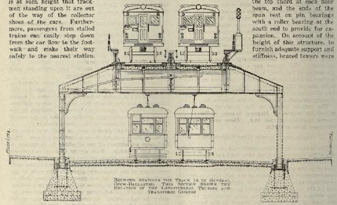 |
| Between Stations the Track is In General, Rock Ballasted. This Section Shows the Relation of the Longitudinal Trusses and Transverse Girders. |
 |  |
| The Center-Column Superstructure in Frankford Avenue Rests Upon Concrete Piers Placed Directly Below the Track Center Lines. | The Car Interior is Well Designed for Handling Rush Hour Crowds. |
 |  |
| The Expansion Joints and Some of the Design Data. | The Storage Yard at Frankford Has Capacity for All of the Rolling Stock of the Frankford Elevated. |
 |  |
| The Inspection Shop is Capacious and Well Lighted. | This Map Shows the Route of the Frankford "L" and Its Relation to the Market Street Line, the Proposed Broad Street Subway and the Newly Built Bustleton Surface Line, Also City-Owned. |
 |
| Substation Architecture is Simple But Dignified. |
 |
| Artistic Street Crossing [Lehigh Avenue] on New Elevated Line. |
 |
| Typical Station on New Elevated Line. |
Signaling on the Frankford Elevated
Electric Railway Journal · Vol. 61, No. 17 · April 28, 1923 · pp 711-715.

Color Light Signals and Automatic Train Stops with Key Release on Frankford Elevated.
The Special Problems Met and How They Were Solved on This Most Recently Completed Elevated Line -- This First of Two Articles Deals Particularly with the Signals, Trips, Electric Circuits and Air Lines.
By J. N. Dodd, Consulting Engineer, New York City. Recently with the Department of City Transit, Philadelphia, Pa.
The Frankford Elevated Railway in Philadelphia is equipped with a complete automatic block-signal system. Some of the main features of the installation may perhaps be most clearly presented in tabular form. They comprise: junction interlocking; yard entrance and terminal interlocking; emergency crossover interlocking; semi-automatic control of interlocking signals; permissive signaling; three-position automatic block signaling; automatic stops; overlap control of signals; electro-pneumatic operation of stops and switches; traffic locking between towers; approach locking; time-release locking; sectional-route locking; speed control of signals; color-light-type signals; single-rail track circuits; A.C. control entirely (no batteries); continuous-bus feed for all low-tension apparatus; loop system of high-tension mains; lever light indicators; illuminated track models.
The signals are of the color light type, with a lens opening 5 in. in diameter. According to specifications they were to have a range of 1,000 ft. in bright sunlight. Actually the range is about 50 per cent in excess of this. Signals at station entrances and "dwarfs" are two-position and display red for "stop" and yellow for "proceed." All others are three-position and show red for "stop," yellow for "proceed with caution as the next signal is red," and green for "proceed." The lamps are 36-watt, 30-volt, and have two filaments in multiple. If either filament burns out the remaining one will give an indication, but the reduction in light warns the maintainer of trouble.
The light unit is a cast-iron box, mounted on a pipe post erected on top of the relay case. The case is carried on a special platform placed just outside of the bench walk running along each side of the structure for its entire length. To one side of the relay case is fastened a ladder to permit access to the light unit.
TRIPS ARE NORMALLY DEPRESSED
On the track level near each signal is a stop or trip which serves to enforce the danger indication. When raised this is in position to engage with a valve in the brake pipe-mounted on the car truck, thus setting the brakes on any car which passes. It is in the raised position only when the red signal is displayed. In general there are two types of circuits controlling trips which are normally in the depressed position. With one type the trip rises directly back of a train and does not fall until the signal changes to yellow. The train is thus protected by two raised trips back of it. The type of control adopted for most of the trips on the Frankford Line differs from this in that the raising of the trip is delayed until the train has left the block at the entrance to which the trip is located. As with the type of control previously described, the trip falls when the signal changes to yellow. The train is thus protected by one raised trip located a full block length back. The presence of a train on the section immediately beyond the trip holds the trip down. This type of circuit was adopted to permit the operation of trains in the reverse direction without the necessity of installing an additional relay at each signal to be operated by the traffic levers in the signal towers.
Relays for this purpose are objectionable on account of their cost, but mainly because they and the control circuits used for clearing stops would come into play only in emergency cases in which it is desired to reverse the direction of traffic. It would be difficult to test out such circuits during the normal operation of the system, as they would be very long and the relays could not be energized without interfering with the normal operation of the trips. If the trips should be disconnected from the relays to test out the relay control, the entire feature would be out of service until the trips were again connected. Because such circuits and relays would seldom be used, and because of the difficulty in testing it would probably often be found that, on account of broken wires or loose connections they were inoperative when needed. The scheme adopted insured that the circuits and relays used will come into play continuously during normal operation. The circuits are local at each station and are therefore much easier to test and maintain.
There is an interesting variation from this type of circuit in the control of the signal trip at the leaving ends of the stations. At these signals there is no overlap and the trip must rise directly back of a train. To avoid using the relays above referred to, the control is such that the trip never rises unless a train enters the approach section when the signal is red.
On the cars of the Market Street elevated line of the Philadelphia Rapid Transit Company, which run over the Frankford line, the valves installed to engage with the track trips are both at the same end instead of one being at each end as is usual. On that line the track trips are normally raised and fall only when a train approaches a proceed signal. Normally raised trips were found unsatisfactory in that a signal could be clear while through some fault the trip was raised and the motorman would find himself stopped without warning when passing a clear signal. Accordingly the Frankford specifications provided that the signals should be red whenever the trip is raised and that the trips should function correctly even when the valves on the cars are placed 38 ft. to the rear of tne front wheels. This necessitated placing the insulating joint 38 ft. back of the signal trip. However the circuits adopted for the trips at the leaving ends of stations made it permissible to place this insulating joint close to the signal.
The trip is raised by a counterweight mounted in a box placed between the rails. The downward pull of the weight is opposed by air pressure in a cylinder. When there is loss of air pressure, or of the electric current controlling the valves, the weight at once raises the trip.
MOTORMAN CAN DEPRESS TRIP FROM CAB
The operating rules provide that a motorman arriving at a danger signal shall stop for a specified short period and shall then depress the trip and proceed under caution. To facilitate his doing so a control button for the trip is mounted on a special stand near the signal, where it can be easily reached from the cab window.
The provision of this control button is an interesting proof of the influence of the men under the Mitten management. When the plans for the new car were finished they were criticised by the men on the ground that there should be a door in the cab to give the motormen access to the station platform and to the bench walk. The men agreed that the main reason for such a door was to permit them to reach the track to depress a trip which was in the raised position. It was impracticable to provide such a door in the car, but instead the equipment just described was installed to allow them to depress the trip from the cab window. It is a feature which has been greatly appreciated by the men.
Affixed to each signal is a number, even or odd denoting respectively the east and west tracks. The number is chosen from the nearest house number on the street. In Philadelphia the house numbers increase by one hundred with every block and a slight knowledge of the city will enable one at once to locate a given house number. Thus signal No. 241 is on the west track near the beginning of block 24. Besides making it easy to determine the location of any signal, this system of numbering eliminates the awkwardness of giving new numbers when the signals are originally numbered seriatim.
Overlap protection is provided at all points, in length not less than the full braking distance required for a train running at the maximum speed attainable if it stops at all stations. With the following exceptions a train is guarded by two danger signals to its rear: A train standing at a station is protected by one danger signal located the full braking distance back. One which has just left the station is guarded only by the danger signal at the leaving end of the platform. The control of the signal at the station entrance is only to the signal at the leaving end and there is no overlap. However, a train which is stopped just after having left a station is protected by the fact that the following train makes the regular station stop and, if the train at the station should accelerate at the maximum rate, the maximum speed which it could attain when it has reached the trip is low and it would be brought to a standstill in a very short distance.
Track circuits are a.c., 60 cycles, and of the single-rail type. The rail next the center of the structure is reserved for the return of the propulsion current from the car motors to the substations, while the outside rail is reserved for the signals. Usually the outside rail is the farthest from the third rail, but it is kept for the signals regardless of the location of the third rail.
Relays are of the vane type. The ruggedness and simplicity of this type render it suitable for the vibrations and other severe conditions experienced on an elevated road. The relays are mounted on springs and enclosed in glass cases which permit an unobstructed view of the interior.
The track transformers are air-cooled and have two secondaries, one for the track circuits and the other for the lights. Each winding has several taps to permit choice of voltages best suited for the conditions met. The insulating joints are Keystone. All other joints in the signal rail are bonded with a No. 2 A.W.G. stranded copper bond, flame-welded to the head of the rail. At each successive insulating joint the polarity of the track circuit is reversed. This permits immediate detection of defective insulating joints.
NOVEL FEATURES IN THE POWER DISTRIBUTION
In the power layout some of the details are perhaps novel. All of the track transformers and other apparatus receiving power at 110 volts are fed from two mains of No. 6 copper running the length of the line. This size was chosen so that if any of the line transformers feeding the mains should burn out, or for any other reason go out of service, the voltage drop through the mains would not be sufficient to prevent any of the 110-volt apparatus from functioning even under the heaviest traffic that the signal spacing will permit.
At each of the line transformers one of the mains is sectionalized by a single-pole switch and fuse. At each of the emergency crossovers, which divide the line into four approximately equal parts, both of the mains are broken by a switch and fuse. Doubt had been expressed as to the feasibility of using continuous mains, so that the switches and fuses were installed to permit sectionalizing if necessary. Up to the present no serious trouble has developed and the mains have been maintained continuous from end to end. The use of continuous mains has been found very satisfactory.
The line transformers are 2,300/110-volt, and are placed at twenty-two different points along the line. At interlockings they are in duplicate. At some of the interlockings the capacity of each is 5 kva.; at all other points, 3 kva. The capacity was chosen such that in case any transformer should go out of service, those on either side would have enough spare capacity to carry the additional load without overheating. All of the transformers are fed through a loop feeder running from the substation to the several transformers and back. At each transformer this feeder is broken by two double-pole single-throw switches connected in series, and the transformer is connected between the two switches. By this arrangement, if any section of feeder should give trouble the switches connecting the section to the transformers on either side may be opened and full service obtained from the transformers through the remaining sections of the loop.
The low-tension wires, including the two mains above described, are assembled in a cable carried in a heavy galvanized steel conduit fastened to the outside ends of the angle irons supporting the bench walk. The cables vary in size from 5-conductor to 42-conductor. Each conductor has a braid over the rubber insulation and there is a double braid over the assembled wires. Braid over each conductor was specified rather than the tape permitted in the Railway Signal Association specifications because it does not untwist in the junction boxes. The taps from the mains across the tracks are 2-conductor cables and all other conductors across the tracks are single wires. Connections from lever machines to switches are 5-conductor cable.
Pull boxes are placed where necessary and in no case farther apart than 500 ft. Expansion joints are provided at junction boxes, transformer and relay cases, and at other suitable points. These are 15-in. nipples of steel pipe 1 in. greater in diameter than the conduit at that point. The end of the conduit is brought within the nipple and there is no screwed connection between the two. The diameter of the main conduits is 2 in., 2i in. or 3 in., as required. The size at all points is such as to permit the installation of 25 per cent more wires than are installed at present. The use of a conduit on the structure for carrying the signal cable was adopted after its value had been demonstrated by eight years' uninterrupted service on the Market Street line. The high-tension feeder is a lead-covered cable carried in the underground duct line.
HOW RELIABLE AIR SUPPLY IS ASSURED
Compressed air is used for the operation of all track trips and switches on the Frankford Elevated. The air pipe is an extra-heavy galvanized-steel pipe 2 in. in diameter, carried in the same manner as the conduit for the cables but on the opposite side of the structure. Expansion is provided for by circular bends, about 3 ft. in diameter, placed not farther apart than 500 ft. At each bend is a 2-in. gate valve.
Drainage of the water which has condensed in the pipe was provided for by installing reservoirs at the bottoms of all slopes and at all expansion bends. These reservoirs are heavy conical castings about 8 in. across the greatest diameter and 10 in. high, supported with the apex downward. The reservoir is carried from the air pipe by a special hanger, as well as by the screwed connection. To remove from the reservoir the water which has collected, a 1/2-in. pipe is inserted to the bottom of the reservoir through the air pipe above it. The opening of a valve in the 1/2-in. pipe allows the air pressure to force out the water which has collected. Reservoirs are connected to the bottom of the pipe and all other connections are made at the top. Every 150 ft. connections are made for the use of air-operated track tampers.
Air is supplied from five compressors of a capacity of 110 cu.ft. each and one of a capacity of 35 cu.ft. These six compressors are located two in each of the three substations which supply power for the road. One of the compressors in each substation is arranged to cut in at a pressure of 75 lb. and the other at 80 lb. Mounted near the compressors is a panel board equipped with an air gage, a voltmeter, a plug and receptacle for connecting the voltmeter to either machine, two d.p., s.t. switches for cutting out either compressor, and a d.p., d.t. switch for connecting either compressor to either governor and so throwing the main load on either machine. Up to the present time one compressor in a substation operating only a small part of the time has been found sufficient to supply the requirements. Excess compressor capacity was supplied to permit the use of compressed air for operation of track tampers and for blowing out snow from the track switches. The compressors are water-cooled, and each is driven by a direct-connected, 600- volt, compound- wound motor.
Fastened to the outside of each substation building is a condenser consisting of thirty-four 1/2-in. pipes 9 ft. long, arranged seventeen in multiple and two in series. The effectiveness of the condenser is shown by the fact that since they have been in operation no water has collected in any of the reservoirs along the line. From the substation to the line the pipe is carried underground, imbedded in 4 in. of concrete.
An article on the signal equipment of this road is not complete without some reference to the work of installation. The order was given on June 6, 1922. Location for the field office, lumber for the shed, and telephone were obtained on June 7. Tools were shipped on June 8 and arrived on June 13. The air pipe, the conduit, the insulating joints, half the trunking and half the signal cases arrived on July 1. The work was finished on Oct. 21, 110 working days after the order was placed. The maximum force was 125 men. The equipment included five interlockings with sixteen switches, seventy high signals, sixteen dwarfs, 7 miles of conduit, 7 miles of air pipe and 1,800,000 ft. of wire conductor. Such an installation constitutes something in the way of a record.
The contractor for the work was the Union Switch & Signal Company. The detail parts were designed and manufactured by this company, which did the entire work of installation.
Credit is due A. O. Smith, signal engineer, Philadelphia Rapid Transit Company, who is responsible for many details of the design, and to E. Baxter and H. Fugitt, of the same company, who were inspectors on the installation work. Stephen Harris, of the Department of City Transit, also had a considerable share of responsibility in connection with the work.
In a later article [below] the interlocking plants will be discussed and attention will also be given to the speed-control signals, which form one of the most interesting features of the installation.
Interlocking Features of the Frankford El
Electric Railway Journal · Vol. 61, No. 18 · May 5, 1923 · pp 762-765.
The Interlocking Features Are Taken Up in This Article, as Well as the Speed Control Signals Which Form a Special Feature of the Installation Junction with Market Street Line Involved Unusual Problems.
In the issue of this paper for April 28, 1923, page 711 [above], the writer explained the layout of the signal system of the Frankford Elevated line, in Philadelphia. He left the subject with an account of the air supply system. There remained to be covered the switch interlocking arrangements and the special problems involved in the connection at Front and Market Streets with the Market Street subway-elevated line of the Philadelphia Rapid Transit Company.
The interlocking plants govern the switches, the "dwarfs," the home signals and, except where the signal is next to the station, they also govern the approach signals. Where a cross-over is adjacent to a station the interlocking governs the approach signal on the side away from the station. The valves controlling the air supply to the switches are of the cut-off type and when the movement is completed they cut off the supply of air to the pistons and thus eliminate the loss of air experienced when the pistons are kept charged at full pressure. Because of restricted space these valves are mounted on a special bracket fastened outside of the bench walk.
Signals for operation in the normal direction controlled by the interlocking plant are of the semi-automatic type; that is, they may be thrown to indicate "stop," but when thrown to the reverse position they act as automatic signals and permit a train to proceed only when track conditions are favorable. Each is equipped with an illuminated dial 7 in. in diameter, bearing the letter T in white on a dark background. The operating rules forbid passing a tower-controlled signal displaying a red light without a special call from the towerman. Accordingly, mounted on the mast is a permissive or "call-on" signal, consisting of a yellow light 5 in. in diameter. "Permissives" and "dwarfs" are non-automatic. They are manually controlled and give a proceed sign only when their controller is operated. Their range is 500 ft. as against 1,000 ft. for the signals for normal operation.
The interlocking machines are 110-volt, a.c., electro-pneumatic. Each machine is inclosed in a steel case having separate, removable doors for each section, to give access to the interior. Signal and switch levers are painted red and black respectively, and project in opposite directions. Levers are equipped with latches to prevent accidental movement, and there is the usual mechanical interlocking between levers. This locking makes it impossible to move a lever until other levers interlocked with it have been thrown to the correct position. Movement of a lever immediately locks the other levers in position before energy can be applied to the unit controlled, and release of other levers cannot be effected until the lever has been thrown to the end of its travel. This locking prevents the throwing of a switch until the signals governing passage over it indicate danger, and in the same way it prevents giving a proceed signal over a switch until the switch has been locked in the proper position and all opposing signals have been thrown to the "stop" position.
For each spare lever, and where space is left for the future installation of a lever, room is left in the locking bed for one cross-locking bar and one longitudinal bar for the full length of the machine.
ELECTRIC LOCK FOR SWITCHES AND SIGNALS
Sectional route locking is provided by equipping each switch lever with an electric lock which prevents the moving of the switch as long as any part of the train is on the section. It is also provided with an indication lock, circuit controlled, so that when the lever is thrown the movement cannot be completed, and thus the mechanical locking affecting other levers be released, until the switch has been moved to and locked in the position corresponding to the position of the lever. Each signal lever is equipped with a similar lock, circuit controlled, so that when the lever is thrown toward normal the movement cannot be completed until the controlling relays for all signals, including permissive, directly controlled and indirectly controlled, have assumed their most restrictive position. The circuits for the signals, as distinguished from the circuits for their levers or relays, are also controlled through relays that positively repeat the position of the switch.
Permissive signals are controlled by a button mounted on the front of the machine and placed directly below the lever for the semi-automatic signal on which the "permissive" is mounted. This button is so interlocked with the lever that the circuit of the "permissive" cannot be completed through its controller until the lever has been reversed. The button also depresses the trip.
Electric locking is also provided to prevent taking away or changing a route after a train has entered the approach sections and the motorman has been given a proceed signal. Under certain restrictions the approach locking can be cut out. The release is by a clockwork mechanism which permits throwing the switch only after the lapse of a predetermined period. This period is adjustable, but the time is made sufficiently long to insure that the train will be brought to a stop before the switch can be moved. Locking which performs the same function is provided in connection with all "dwarfs" and with certain semi-automatic signals for which approach locking is not provided. This, however, is always effective, and is not dependent on the presence of a train in the approach section. This locking has automatic time release.
There is a sealed clockwork release for each electric lock on switch levers. This makes it possible to throw a switch when a car is on the section, but only after the seal has been broken, and it is impossible to give any proceed signal other than a permissive over a switch unlocked in this way.
Under each switch lever is a visual indicator of the electric-light type, which indicates by a green light that the track circuit controlling the lever is unoccupied and that the lever may be moved. Under each signal lever controlling a semi-automatic signal is a similar indicator which shows by a green light that the track circuit controlling the semi-automatic signal is unoccupied. It is also provided with a red light. When the lever is thrown this light indicates by a flash that the relay controlling the signal has responded. Incidentally if a train is on the section and the signal therefor indicates "stop," although the lever has been reversed, this light will give a continuous indication.
PROVIDING FOR REVERSE-DIRECTION TRAFFIC
There are four traffic levers on each machine. Each lever in conjunction with a similar lever in an adjacent tower permits the establishment of a reverse direction of traffic on a track between the two towers, but only when the levers controlling the signals at the entrance to the controlled territory are normal and the signals indicate stop and at the same time the controlled territory is unoccupied. They are provided with locking which does not restrict non-conflicting train movements, but permits following trains in the established direction at close intervals. Under each traffic lever is a visual indicator which shows by a green light when conditions are proper for change in direction of traffic, and the lever may be reversed.
Mounted on an angle iron frame directly above each machine is an illuminated model showing tracks, track sections, signals, and other features of the interlocked section. Each track circuit on the model is colored sufficiently distinctive to differentiate adjacent sections. It is also indicated by a round spotlight located approximately at the middle of the section it repeats and which burns only when the track section is unoccupied. The model has one light for each track section within interlocking limits, one for each of the approach blocks and one for the receding track territory controlling the home signal at the entrance to the switch.
Near each machine is a switch panel carrying the following instruments: one voltmeter for the 110-volt mains, one air gage, two ground detectors and one switch for tower lighting.
SPECIAL PROBLEM AT FRONT AND ARCH JUNCTION
Special treatment was found necessary for the junction at Front and Arch Streets, between the line from Frankford and that from the ferries. At a junction point the signal layout must be such as to insure a specially high track capacity. It is true that, except for interference between trains running in opposite directions, if trains are run to schedule there will be no more congestion at a junction point than at other points of the line operating the same schedule, but it is also true that on a rapid-transit line trains cannot be run exactly to schedule. One train will stop at a station for say ten seconds, while the following train may easily be held for as long as ninety seconds. By proper dispatching at a number of points these differences may to a certain extent be smoothed out.
However, the junction at Front and Arch Streets is next to the Market Street station, which is served by the ferries of the shore lines of the Pennsylvania and Reading Railroads. During the summer these roads operate a frequent ferry service and most of their passengers take the elevated cars. It frequently happens that when a train enters a station there will be waiting on the platform the passenger loads from three ferry boats, and while these are loading on the train a fourth boat arrives and delays the train even further. When the next train arrives the platform is empty. Delays of trains approaching junction points are. unavoidable, and if the signals cannot handle the trains as they arrive from the two lines there will be congestion.
The necessity for capacity at the Front and Arch Streets junction is accentuated by the fact that there will be interference between trains going in opposite directions. The tracks for Frankford and those from tlie ferries cross each other at grade. This interference delays the service on one line and, therefore, of all cars in each direction that pass the junction. The signal installation must be such as to handle, without delay, trains running at very close intervals.
The grade and alignment of the road at this point make it difficult to signal the line for high capacity. Rules for laying out signals call for rear-end protection not less than the distance necessary to stop a train running at the highest attainable speed. A line where the stations are at the tops of grades is easy to signal for close traffic. On the down grades from the stations the block lengths must be long but the speeds are high so that heavy traffic can pass. On the up grades into the stations the speeds are low but the block lengths are short. Either of these combinations permits close running.
However, when the stations are at the bottoms of grades it is difficult to signal for high capacity. The trains can reach a high speed on the down grade, so that with the ordinary methods of signaling very long block lengths are necessary. Practically, on a steep down grade terminated by a station, the trains actually run at a very low speed as the motorman is afraid to let his train out of control. The combination of low speed and long blocks prevents close running.
The grade and alignment at this point are such as to present to the trains from Frankford a danger condition which does not exist to the same extent for the trains from the ferries. As the ferry trains start from Market Street station they immediately encounter a curve of 140 ft. radius, with a total angle of 180 deg. by which the road reaches Arch Street. This curve terminates in a 5 per cent down grade leading into the subway. At the lower end of this grade is a curve of 200 ft. radius, with a total angle of 90 deg. at the end of which is the station. While these conditions are extreme, no accident has occurred here in the fifteen years of operation. The curve of 140 ft. radius is within full sight of the motorman as he starts from Market Street and he will not accelerate rapidly to it or run fast around it. Before the rear of his train is off the curve he is well down the grade and close to the 200-ft. radius curve. The layout itself guards against excessive speed on the grade.
For the trains from Frankford a different condition is presented. The grade terminates a long straight run. At the beginning of the grade is a 2.35 per cent slope; then there is one of 4.6 per cent which leads into the 5 per cent slope, at the lower end of which is the curve into the station. Except for the curve at the foot there are no natural obstacles to high-speed running and it would be easy for a motorman to attain a speed on the grade from which it would be impossible to brake to a speed safe for the curve. The blocks on the curve should be long to avoid rear-end collisions. On the other hand, the trains must run slow to avoid disaster on the curve. With the usual signal layout the track capacity would be low, whereas, as has previously been pointed out, a high capacity is essential. Moreover the usual signal layout does not prevent high speeds. A signal system was necessary which would guarantee safety and capacity.
SPEED CONTROL SIGNALS SOLVE THE DIFFICULTY
The solution determined upon was to provide double overlap so as to space the trains closer and to install "speed control" signals. These are signals which normally display a danger indication, but are equipped with a time element which causes them to display a proceed signal a certain number of seconds after the time element has been energized. This time element is essentially a constant-speed motor.
The type of speed control usually installed is two-position, and has a single control. This is energized when the approaching train enters the block, immediately in advance of the signal. It is entirely effective in limiting the speed, but it is open to the objection that it keeps the speed of the trains to too low a value and makes it impossible to get the traffic over the line. The motorman, seeing the danger signal ahead, takes no chances of being tripped but runs at such a low speed that the signal clears well ahead of him. Experience shows that the average speed of trains over a line equipped with this type of speed control is only about half the permissible speed, and this reduction in speed cuts into the capacity in about the same proportion.
The speed control signals decided on for this installation are three-position with two controls. The time element becomes energized when the front of the approaching train enters the second block in advance of the signal, and the yellow proceed signal is displayed a certain number of seconds thereafter unless before this time has elapsed the front of the train has entered the block immediately preceding the signal. If it has entered this block the signal under consideration will continue to display red and its trip will continue raised until a predetermined period of time has passed, after the train has entered this last-named block. These two periods of time are independently adjustable.
Experience in New York, where this type of speed control signal was developed, show that where it is installed the speed of the trains is very close to the limit for which the signals are set. Trains usually pass the signals just at the instant they flash from yellow to green and the one ahead changes from red to yellow. If the train runs too fast and passes a signal before it changes to green, the motorman checks the speed only slightly and the next signal is reached just after it changes from red to yellow and from that to green. It is almost as if the motorman accepts the signals as a sporting challenge to run the train at the speed for which the signals are set.
A criticism against this type of signals is that they do not make high speeds impossible. Theoretically this criticism is true. If the motorman is running at the correct speed the nearest raised trip is always the second one in advance. It is possible for him to accelerate over this space at the maximum rate and to attain a high speed before he is tripped. However, this criticism is more academic than real. The signals normally indicate danger at all times of the day and in all conditions of traffic. The motormen come to accept them as part of the existing conditions just as they accept the stops at stations. It is as difficult to conceive of a motorman throwing on full power and running into a signal which he knows always indicates danger as it is for him instead of stopping at a station to rush through it at full speed when he sees a train stopping just beyond it.
To sum up, the speed control signals are such as to cause the motorman to run no faster than the predetermined speed but to encourage him to run close to it, and in this way to obtain full capacity for the grade. It will be noticed that these special precautions cover the safe operation down the grade of trains running at close headway. They do not cover safety at the grade crossing. The precautions to this end are simple. The crossing movement is between trains from the ferries and trains to Frankford. Safety for this movement is insured by mechanical locking in the lever machine so that the switch cannot be thrown for the train to Frankford if the position of the switch on the other track permits the passage of a train from the ferries. Before the route can be set up for the west-bound train from the ferries, the switch on the east-bound track must first be thrown and locked so that the only east-bound movement possible is to the ferries and a crossing is impossible.
As was mentioned at the end of the preceding article the contractor for the signal system of the Frankford Elevated was the Union Switch & Signal Company. This applies to the features covered in the concluding article as well as those described earlier.
 |  |
| At Left, Expansion Loop and Drainage Reservoir in Air Pipe Lines. At Right, Condenser for Removing Moisture from Air Pipe Lines. | Pair of Motor-Driven Air Compressors in Substation. |
 |
| At Left, Another Color Light Signal with Train-Stop Key-Release Pedestal. In Center, "Close-Up" of Automatic Trip for Stopping Train When Signal Is Ignored. At Right, Vane Relay, Transformer and Reactor, Mounted in Case. |
 |
| At Left, Steel Relay Cabinet and High-Tension Transformer in Substation. At Right, Transformer for Supplying Signal Current, Together with Fuse Boxes, Mounted in Cast-iron Case. |
 |  |
| Map of Frankford Elevated Line In Philadelphia Showing Relation to Market Street Subway. | Terminal Board in Signal Circuits, In Cage Hung from Walkway Railing. |
 |
| Automatic Train Stop, Color Light Signals, and Switch and Lock Movement, Electro-Pneumatic Interlocking, on Frankford Elevated. |
 |
| [Left] Color-Light Signals at Torresdale Street Electro-Pneumatic Interlocking. [Right] Another Installation of Color-Light Signal at Interlocking on the Frankford Elevated. |
 |
| Electro-Pneumatic Interlocking, with Switch and Lock Movement, and Color Light Signals at Dauphin Street, on Frnnkford Elevated. Inset, Close-Up View of Switch and Lock Movement on Frankford Elevated. |
 |
| High and Dwarf Color-Light Signals and Automatic Train Stops at Entrance to Market Street Subway, Junction of P. R. T. and Frankford Lines. |
 |
| Electro-Pneumatic Interlocking Machine, with Lever Light Indicators and Illuminated Track Model and Clockwork Time Releases. |
Sources
Electric Railway Journal, McGraw Hill Company, Digitized by Microsoft, Americana Collection, archive.org.