Boston Elevated Railway Company, Main Line Elevated Structure (HAER)
![]()
Green Street station of the Main Line Elevated, looking north along platform. Photo by Richard Cheek/Historic American Engineering Record, 1982.
Boston Elevated Railway Company, Main Line Elevated Structure, HAER No. MA-14
INTRODUCTION
The extant (1986) portion of the original elevated Mainline of the former Boston Elevated Railway Company (BERy) is located on Washington Street, in the South End, Roxbury and Jamaica Plain districts of Boston, Mass. and runs between the South Portal of the Washington Street tunnel and the Forest Hills Station, repair shops, and storage yards (Bents #1215 to #772). The original Mainline of the Boston Elevated Railway ran from Sullivan Square, Charlestown to Dudley Street, Roxbury and was later extended to the Forest Hills Station. George A. Kimball was the Chief Engineer for the former Boston Elevated Railway Company, 1898-1901 and 1906-1909; the structure was built as follows: Sections F-1 through F-4: 1898 - 1901; Sections F-5 through F-6: 1906 - 1910; Section F-7: 1921 - 1923.
[The Atlantic Avenue portion of the elevated was removed in the 1940s; the northern portion from Charlestown to Everett was removed in 1975.]
The remaining structure consists of six stations. Bent numbers are indexed on plans in the files of the Massachusetts Bay Transportation Authority (MBTA) Engineering Department. Grid Coordinates refer to the Boston South Quad.
- Dover Street; Bents #1174-1181; 19.0329780E.4689820N
- Northampton Street; Bents #1093-1098; 19.0328880E.4689000N
- Dudley Street; Bents #1024-1040; 19.0328260E.468825ON
- Egleston; Bents #908-915; 19.0328030E.4686760N
- Green Street; Bents #857-864; 19.0326500E.4686070N
- Forest Hills; Bents #783-789; 19.0325780E.4685100N
Remaining portion of the original BERy elevated Mainline Structure is currently in use as part of the MBTA's Orange Line rapid transit service from Forest Hills to Medford, Mass. The elevated portion (Section F-1 through F-7) serves from the South End through Jamaica Plain. The entire structure is slated for demolition when the new Southwest Corridor segment of the Orange Line rapid transit is completed in 1987.
This portion of the Orange Line elevated is historically significant as Boston's first elevated line, built during a period of world-wide interest and experimentation with elevated railways; and as the product of Boston's last privately-owned transit company, the Boston Elevated Railway Company. It is also the last remaining portion of a formerly extensive elevated rapid transit system built at the turn of the century in Boston.
Architecturally, it is significant for the quality of its original station architecture, which was designed by the prominent local architect, Alexander Wadsworth Longfellow. Later alterations were carried out under consultation with other leading Boston architects, such as Robert Swain Peabody and Edmund Wheelwright. In general, it represented the most advanced transportation planning of its day and is a good case study, on a small scale, of rapid transit at the turn of the century.
DESCRIPTION OF SECTIONS
The Mainline of the BERy at one time consisted of six sections which traversed the congested areas of Boston and Charlestown to Roxbury and Jamaica Plain. For convenience these sections will be categorized alphabetically, according to their original locations, and hereafter will be referred to by Section letter. The main body of this report concerns Section F. The sections are indexed on plans of the former BERy, MTA and the current MBTA.
Section A. Formerly the Charlestown Division of the Boston Elevated Railway Company (BERy). Constructed in 1898-1901. Sullivan Square Terminal southerly through Charlestown to the North Portal of the subway. Included City Square, Thompson Square, North Station stations and the Charlestown drawbridge over the Charles River (built in 1896-1899 by the Boston Transit Commission). This section was abandoned in 1975 and was demolished in 1976-1977 when the new Orange Line subway was extended to Medford along the Boston and Maine Railroad right of way. Only Tower "C" was saved from demolition and moved to the Seashore Trolley Museum at Kennebunkport, Maine.
Section A-1. Extension of the Charlestown Division line easterly into Everett. Constructed in 1916-1919. Included only one station -- Everett (built by the BERy). Discontinued in 1975 and demolished in 1976-1978.
Section B. North Portal to Pleasant Street Station (now Broadway) via the outer tracks of the Tremont Street Tunnel which was adapted to elevated train use in 1901 by the construction of higher platforms. This link was returned to full streetcar use in 1908 with the construction of the Washington Street Tunnel.
Section C. Pleasant Street Station, up the incline, over the Boston and Albany and New Haven Railroad right-of-way tracks, and along Castle Street as an elevated structure, to Tower "D" (Bent
- 1200) on Washington Street. Constructed by the BERy in 1901 to link
the Washington Street elevated to the South Portal of the Tremont Street Subway. Abandoned in 1908. Demolished in 1935. Incline portion remained until demolition in 1961.
Section D. Elevated structure along Atlantic Avenue from Tower C at North Station to Tower D at Washington Street. Constructed in 1901 and in use until 1938. Demolished in 1942.
Section E. North Portal to South Portal via Washington Street Tunnel. Built in 1904-1908 by the Boston Transit Commission. This section will continue in use after demolition of the elevated structure.
Section F. South Portal to Forest Hills repair shops. This line was originally known as the Roxbury Division of the BERy. The line is divided for identification purposes into the following sub-sections:
Section F-1. South Portal (Bent #1215) to Tower D at Washington Street. Built in 1908 by the BERy to connect the new subway tunnel to the Washington Street line of the Roxbury Division. Structural system is plate girder bents with longitudinal plate girders.
Section F-2. Tower D at Bent #1200 to Bent #1143 south of Dover Street Station. Built between 1899 and 1901 as part of the BERy Roxbury Division to Dudley Terminal. Plate girder bents with longitudinal truss girders.
Section F-3. Bents #1143 to #1068 along Washington Street. Built between 1899 and 1901 by the BERy. Includes Northampton Street Station. Arched truss bents with longitudinal truss girders.
Section F-4. Bents #1143 through #1100 to the Bartlett Street Yard. Built in 1899 to 1901 by the BERy as part of the original Roxbury Division. Includes the Dudley Terminal and the Guild Street yards and repair shops (discontinued in 1923). Plate girder bents with longitudinal truss girders. Loop around Dudley Station is marked by Bents T-1 through T-28.
Section F-5. This section is the beginning of the Forest Hills Division. Construction work began on May 2, 1906 and service began on November 22, 1909. Work included rebuilding the loops and platforms at Dudley Street Station and the construction of Egleston Station. Section F-5 runs as an elevated structure from Bent #1000 to
- 797 at the Arborway yards. Construction is plate girder bents with
plate longitudinal girders. Green Street Station was added on as a suspended structure in 1912.
Section F-6. This section was a specially designed steel framework encased in concrete. Bents #979 to #783 include Forest Hills Station. Built in 1908-1909 by the BERy.
Section F-7. Bents #783 through #772 constitute the Forest Hills train storage yards and the repair shops. This extension was built in 1921. Repair shops built in 1923. Includes Tower "H". This section was demolished in 1984.
CHAPTER 1, Introduction and Significance of the Orange Line Elevated
Ever since Boston's earliest days Washington Street has been the main route for transportation between Boston and Roxbury and all other towns in the southwest portion of the larger city. The earliest stagecoach followed by the omnibus and later by horse-drawn and then the electric streetcar all used this route that was to become so heavily travelled that by the 1880's it had become imperative to build an elevated railway to provide rapid transit north and south of Boston. This section of the elevated structure from Dover Street to Forest Hills is the last remnant of a larger system of elevated railroads that served Boston at the turn of the century.
Boston was one of the last major American cities to build an elevated rapid transit line. The system was developed first in New York City and refined in Chicago, where third-rail electric motive power was first used. Because it was built comparatively late, the Boston Elevated structure could use advanced rapid transit technology borrowed from many different sources. It is today a good case study, on a small scale, of the "State of the Art" of rapid transit at the turn of the century.
The Orange Line is significant not only from the point of view of technology but it also represented the most advanced transportation planning of its day. The BERy was the first company in the United States to include subways, elevated transit and surface trolleys -- all operating under one management. In contrast to a system with many competing lines and companies (the usual situation in most cities), the public could transfer from one section to another of the BERy without paying more than one fare.
The early history of the Boston Elevated Railway and the Orange Line illustrates how Boston avoided the excesses of both total public control and free-wheeling private enterprise. All major cities building transit systems at that time had such problems in common, but in Boston a balance was struck: private management ran the system but government regulated it and also built the subways.
Although it was a small system, Boston's distinctive topography caused many difficult planning and engineering problems. Narrow curving streets, high density in the downtown area, limited arteries into the center of Boston, the hilly terrain, the Boston Common and Public Garden, and settled residential districts made the task difficult for the Civil Engineer. Contemporary descriptions of the system continually extolled the work. It remains today an impressive undertaking. By studying this system today, we learn on a modest scale about the problems of other transit systems of that era. We can also more fully appreciate the engineering capabilities that built this system.
CHAPTER 2, The Story of Early Public Transportation in Boston
Until the mid 19th century, Boston was a peninsula surrounded by water on three sides and connected to Roxbury on the south by a neck of land. Cambridge to the west and Charlestown to the north, connected to Boston by bridges, were the only other important communities. People lived close to their work and rarely travelled beyond their own communities. Except for private coaches and horses for the well to do, stagecoaches, omnibuses and, later, trains were the only methods of distant travel.
The omnibus, a horse-drawn bus with a rear entrance, was the first form of public transportation running on a regularly scheduled basis. In 1826 the first omnibus line in Boston opened. This ran to Cambridge, and by 1830 there was a similar line to Roxbury. Both were privately operated. These early omnibus lines used approximately the same routes as at least two of the major branches of Boston's later public transportation system: The Red Line serving Cambridge/Boston and Orange Line serving Roxbury/Boston/Charlestown.
In 1856, the first horse-drawn street cars were introduced from Harvard Square, Cambridge to Bowdoin Square, Boston. Although steam railroads had been operating since the 1830s under charters from the Massachusetts Legislature, their service was limited largely to routes between cities and towns. By the middle of the century, Boston's population had increased greatly and there was a pressing need for rapid transit within the city.
The first such company was the Cambridge/Boston Company (1856), followed by the Metropolitan Railroad Line. This change underscored the evolution of Boston from a compact mercantile city to a larger one fed by the suburbs. Horse railways operating under a public franchise offered a faster and more comfortable ride than the omnibus. Under Massachusetts law, a franchise was a revocable right, granted by a municipality, to operate over public roads; thus the public had some control over the privately operated horse railways.
The Legislature and the Boston City Council subscribed to the then universal belief that free competition among many companies on public streets would provide the best service for the general public. In most large cities, especially New York and Chicago, there were many independent lines spread out over a wide geographical area. In spite of municipal corruption, the traction franchises still ensured reasonably good public service.
In Boston, because of local topography, the situation worked out differently. All traffic from the north and south was funnelled into the downtown along the two main downtown streets: Tremont and Washington. As Boston's population and business district grew, the surrounding towns became bedroom suburbs, and in turn caused the public transportation system to become overloaded.
By 1865 there were four main horse street railways:
- The Middlesex Railroad - serving the North (Charlestown);
- Union Railway - serving the West (Brighton, Cambridge, Somerville, Watertown, and Arlington);
- Metropolitan Railroad - serving the Southwest (Brookline, Dorchester, Roxbury, West Roxbury);
- South Boston Railroad - serving the South (South Boston, Dorchester).
In 1872 and 1881, the Highland Street Railway, serving Roxbury and Dorchester, and the Charles River Railway, serving Cambridge and Boston were established.
The lines were largely independent, and there were few crosstown lines or transfers. In the congested downtown area, the lines had to share a few tracks along Tremont and Washington Streets. Fragmented service and competing lines were not the answer to Boston's expanding business growth and population.
By 1860, traffic was 50 million riders, and, in 1885, it had climbed to 80 million. All large American cities had similar transportation problems and tried various solutions. In 1873, the cable car was invented in San Francisco and quickly was adopted in New York, Chicago and Washington, D.C. The horse-drawn street car had reached the limits of its effectiveness. It could not travel long distances at a high speed or carry heavy loads of passengers, and the cost of maintaining large stables of many horses was becoming prohibitive. The cable car was the first practical method of increasing the effectiveness of mass transportation. Although the cable cars worked well in cities with broad straight avenues, they were not feasible on Boston's crowded streets, which had to carry several lines.
In Berlin, in 1881, Werner Siemens put into operation the world's first electric streetcar. This was followed by various attempts by Charles Van Depoele and Leo Daft in the United States to develop a workable electric streetcar. The rapid development of technology in the 1880s provided a solution. The first practical electric streetcar system was realized by Frank Julian Sprague in Richmond, Virginia in 1887 -- a major step in transit history.
Meanwhile in 1886, Henry Melville Whitney, Eben Jordan and others had purchased a vast amount of land along Beacon Street in Boston and Brookline to develop as real estate. They also chartered the West End Railway to provide street car transportation into Boston. Whitney soon realized that all seven of the then competing roads would have to be combined into one economical line. His strong financial backing and his political role as an enlightened Democratic business man gave him the legislative support to create the requisite transit monopoly in Boston and its major suburbs.
Whitney, in less than a year, had organized the seven separate lines into a single integrated transit system using the "division system" of organization employed by major railroad companies. The best executives from the old lines were placed in responsible positions within the new company.
Frank L. Sprague's success with the electric street car in Richmond, Virginia convinced Whitney that electric traction was the solution to the shortcomings of the horse cars. He electrified the Beacon Street Line of the West End Railway in 1887, making Boston the first major city in the world to employ electric streetcars. By 1892, the trolley cars accounted for two thirds of the city use, and, by 1894, more than 90% of the lines were electrified.
Contemporary accounts describe the progress of the West End: Within a single year this company, through the financial genius of its organizers, had accomplished the consolidation of all the great street railway companies of the city, operating 231 miles of track, the largest street railway system in the world.... It is probable that more problems of mechanical engineering and of railway administration have been grappled 'ab initio' by this one company than by any other team of street railway companies in the last fifty years. [1]
Although the West End provided excellent transit service, there were still problems. Ridership kept increasing, and the number of persons and streetcars going into downtown Boston began to choke the downtown streets again. There were many proponents of an elevated railroad to provide rapid transit. This had been the solution in New York City, where the first elevated railroad powered by steam locomotives was built. Chicago, another city with broad, long avenues, also had a network of elevated railroads beginning in 1892. Most Bostonians did not want the noise and ugliness of elevateds in downtown Boston, but the residents of outlying sections of the city were in favor of an elevated railroad that would shorten travel time into Boston. Charles Cheape has chronicled the complex struggles that went on in Boston as the public sought a solution to the traffic jams in downtown Boston. [2]
In 1891, the Legislature set up a Rapid Transit Commission to resolve the transit impasse. After many hearings and much research, the Commission made several recommendations for Boston's future transportation system. Three recommendations were especially important:
1) North and South Stations should replace the numerous railroad stations then serving Boston; 2) An electric streetcar subway should be built under Tremont Street; 3) A system of elevated and subway lines should be built to Charlestown, Roxbury, Cambridge, and Boston.
Stat. 1894 Chap. 548 -- An Act that incorporated the Boston Elevated Railway Company (the "Meigs Charter") and authorized numerous transit routes in the Boston Metropolitan area -- was the first regional approach to mass transportation. Later Acts were: 1) Stat. 1895 Chap. 440 -- An Act that authorized the construction of subways in the City of Boston; 2) Stat. 1896 Chap. 492 -- An Act that placed limits on the West End Railway in its use of the subway; 3) Stat. 1897 Chap. 500 -- An Act that authorized the Mass. Railroad Commission to use other systems besides the Meigs. This law also: a) Authorized construction of the Cambridge Subway; b) Laid out routes of a proposed elevated railway; c) Gave the Mayor of Boston authority to review and approve architectural and engineering plans of an elevated railway; d) Established a five-cent fare with right of free transfer; e) Required that the elevated railway run through a subway in the center of Boston; f) Authorized construction of a new rapid transit bridge from Boston to Cambridge across the Charles River; g) Authorized construction of a rapid transit tunnel to East Boston under Boston Harbor; h) Declared franchise rights of the BERy to be irrevocable.
This was an unusually comprehensive and well thought out law that resolved most of Boston's transportation dilemmas. From this point on, good public policy and sound traction management were to be characteristic of the city's transportation system for many years to come.
After Henry Whitney left the West End Railway in 1893, that company lost its strong direction and failed to take advantage of the new legislation. A competing group of financiers headed by J. P. Morgan bought out the old Meigs franchise through the Boston firm of Kidder Peabody in 1895. The new directors had the requisite backing to finance construction of the "Elevated." They also proved able to overcome the public's objection to the structure. After some maneuvering, the Morgan group bought control of the West End, which, on December 9, 1897, was absorbed by the Morgan run Boston Elevated Railway. The new BERy now had both a financial and legal monopoly over most public transportation in Boston and its suburbs.
The Act of 1897 also resolved the dispute over the location of the Elevated structure. In 1895, the Boston Transit Commission had begun construction on the Tremont Street Subway, which opened on September 1, 1897. The new charter allowed the BERy to use the Tremont Street Subway for its elevated trains. This solution prevented the disfigurement of downtown Boston by elevated tracks while providing for their construction in the outlying suburbs of Roxbury and Charlestown.
The creation of the West End Railway and the BERy had understandably caused many reform minded individuals, led by Louis D. Brandeis, to fear that these giants would abuse their potential monopoly powers. It was a complex dilemma. There was little confidence in the ability of the often corrupt municipal governments to operate public transportation. Therefore the prevailing sentiment favored private enterprise. Yet only a company with near total monopoly powers could operate rapid transit systems effectively. Boston's eventual solution of public and private control was unique in the United States.
In other major American cities, traction companies managed to wrest total control from the public. By contrast, in Europe, municipal governments subsidized and completely controlled public transportation.
In Boston, the public component was the Boston Transit Commission chartered by the State Legislature. The Commission built the subway and leased it to the BERy to be used by its rolling stock. Thus the major capital expenditures for Boston Elevated Railway Company subway construction (more costly than an elevated structure but more desirable for use in the downtown area) would be undertaken by the City of Boston using its lower interest rate on bonds. The BERy, with the approval of, the State and the City, then built the elevated structure and connected it to the subway. With its impressive financial resources, it could build the structure, the stations and the outlying street lines and operate the entire system. The public benefited because the monopoly was partially under control of the electorate. The individual rider benefited more directly from the five-cent fare and the right of free transfer.
CHAPTER 3, Construction of the Elevated Structure 1898-1901
Once the legal problems surrounding the granting of a clear charter to the Boston Elevated Railway and its franchise to build a third-rail, electrically operated, elevated rapid transit system (using the then new multiple unit cars) had been resolved, the management of the BERy immediately began planning work for the proposed elevated structure.
George A. Kimball (1850-1912), a respected local civil engineer, was appointed chief of the Engineering Division to plan, design and construct the elevated railway. Kimball had served for eleven years as chief engineer for the City of Somerville and had gone on to distinguish himself as the engineer for the Metropolitan Sewage Commission. In the 1880's this agency had been primarily responsible for building a vast regional sewage system for metropolitan Boston -- a major civil engineering feat for its day.
Under the terms of Chap. 500 Acts of 1897, the BERy was first required to submit plans of the route to the Massachusetts Railroad Commission, which at that time was empowered to supervise all railroads and street railways, for review and approval. The plans then had to be approved by the Mayor and Common Council of the City of Boston.
The main public criteria were that the structure be light and airy and that the stations be of superior architectural appearance. Although New York City had been constructing and operating elevated railways since 1873 and Chicago since 1885, Boston was just now accepting this already standard form of rapid transit. New York's system of steam locomotives pulling wooden railroad cars had not impressed Bostonians. The structure of the New York Elevated, though elegant and open in the early stage of development, became less attractive as solid plate girders were used in the later extensions. The combination of noisy, smoky, dirty trains runnning over structures that blocked out the sunshine on the streets below was something that Bostonians wished at all costs to avoid.
Moreover, with its sophisticated architectural and civil engineering forms, the Berlin elevated railway system set a standard of excellence which Bostonians tried to achieve. [1] The BERy executives made every effort within their limited budget to avoid the mistakes of the New York systems and to emulate the successes of the Germans.
The basic design of the elevated structure was quite similar to the one developed in New York City and later perfected in Chicago. The preliminary designs were done under the direction of J.A.L. Waddell, who had been primarily responsible for the design of the Chicago system. The structural and civil engineering work was done by the Engineering Department of the Boston Elevated Railway Company. (Chapter 6...Structural Analysis and Description of the Elevated Structure discusses in greater detail the engineering aspects of the elevated structure.)
In general, the tracks were laid 24 feet apart on center except on narrow streets where they were 12 feet apart. The rails were 85 lbs ASCE Boston Elevated Railway Company sections spiked to hard pine ties 16 inches on center, which in turn were bolted to the steel structure. Every fourth tie was extended out to support a sidewalk for track maintenance men. The trackwork was supported on bents consisting of steel columns supported on heavy concrete foundations. Heavy cross girders connected the columns and longitudinal girders with cross bracing supported the tracks. After a long design review process, the final approval for the system came on April 29, 1898.
Construction began on the Dudley Station site on January 23, 1899. Property condemnation proceedings had already commenced allowing for demolition of any structures in the way. Contracts for steel work along the Roxbury Division were awarded primarily to the Pencoyd Bridge Co. of Pencoyd Pennsylvania, a noted bridge building company, which already had considerable experience with the then new steel technology of fabrication and construction. Other steel work was executed by the Carnegie Steel Co. and the Pennsylvania Steel Co. Terry and Trench Co. of New York City were selected as general contractors for the steel erection primarily because of their experience in putting up elevated railroad structures in New York City.
While construction on some parts of the Elevated, in Charlestown and on Pleasant Street and Atlantic Avenue, was carried on in a normal fashion during the day, most of the work on the Washington Street segment was done at night. While efficiency and speed were considerations, the main reason was to avoid touching the live wires that fed the trolley cars running along Washington Street. (The lines were either removed from the portion under construction at night or else the power was cut.)
The BERy specifications stipulated that, wherever there were surface tracks, materials should be delivered to the narrow portions of the streets each evening after 7pm and that construction could take place only between the hours of midnight and Sam. Columns and girders were fabricated in the Shops of the bridge companies doing the work, delivered by railroad car to the nearest siding and finally hauled to the site by trucks pulled by horse teams. Photographs show how the first columns were erected on Washington Street near Dover Street. After the cross members were in position, a traveller was installed to lift succeeding bents into place. Incandescent lights were also hung from the traveller. All steel members were riveted together. As each bent was set into place and the longitudinal girders attached, the traveller pulled itself forward along the tops of the girders on rollers to the next stop and installed the next section.
The work was carried out in five segments:
a.) The Charlestown Main Division;
b.) The portion over the Charlestown Bridge which itself had been built in 1895 by the Boston Transit Commission;
c.) The conversion of the Tremont Street Subway, which originally consisted of four tracks for streetcars and was modified by the BERy to allow use of the high platform third rail trains on the two outside tracks;
d.) Building an inclined connector between the tunnel portal at Pleasant Street across the Boston and Albany Railroad tracks and Tower D at Washington St.;
e.) The construction of the Roxbury Main Line along Washington Street (now called the elevated portion of the Orange Line) to the terminal at Dudley Street.
The line was planned as an elevated rapid transit railway between several stations spaced at long intervals for passengers arriving by surface streetcars. Since Boston streets were too narrow to allow more than two tracks, the New York and Chicago system of four-track lines consisting of express trains and local trains was not used. Since the BERy also had the unique advantage of controlling all local lines with the right of free transfer, the system of a limited number of stations spread far apart was feasible. The Roxbury Division was planned to service local lines at Dover Street, Northampton and finally Dudley. These street car lines served Brookline, Newton, Dorchester, Roxbury, Jamaica Plain, South Boston, and connected to other companies serving communities to the southwest of Boston as far as Walpole. Lines that formerly ran into downtown Boston either along the streets or, after 1898, through the Tremont Street Subway were now serviced by the Elevated, thus cutting down the time of travel.
Construction on the Castle Street/Pleasant Street connector began in the fall of 1900 just as the work on the Pleasant Street portal and the new viaduct was mostly done. Construction photographs show the rapid progress of steel erection during December 1900 and January 1901. To accommodate the longer multiple unit, three car trains inside the Tremont Street Subway, the outer two tracks were converted to third-rail use; and, inside each Subway station, high wooden platforms were erected to allow direct access to the trains. Since the Subway had been designed with short trolley cars in mind, some of the radii were too tight, and certain walls and platforms had to be modified to allow clearance for the new trains. Most of the conversion work was done in the Subway in the week prior to the opening of the new elevated line in order to minimize obstruction to trolley cars using the Subway.
Steel erection on the Washington Street section began on August 19, 1899, and, by December 20, 1899, the structure had been erected as far as Sterling Street -- a remarkably fast performance by today's construction standards. (In 1980, a modern flat plate girder replaced the existing trussed girder to allow for the passage of the new Melnea Cass Boulevard under the structure.)
Project planning was done under what we now call a fast-track method. As soon as planning approvals were obtained, structural design and detail drawings were begun, and contracts were signed with steel companies for the required tonnage of steel. First column foundations were poured. Erection of the structure began as soon as possible. The main line structure was already up while architectural drawings for the stations were being completed. A completion date of December 1900 had originally been scheduled but was delayed a few months. The construction progress photographs show a last minute push in the winter of 1901 to finish the stations and other facilities. Concurrently with this work, the BERy was erecting the Atlantic Avenue loop (Section D), which joined the North and South Terminal Railroad stations and created a downtown transit circuit through the Tremont Street Subway (Section B).
Dover Street Station was built in 1900 as a center platform type of structure. Like Northampton Street Station, it was designed to be used by four-car trains. After the opening, traffic on the elevated line was so heavy that the BERy decided to lengthen the station platforms to accommodate six-car trains originally and eight-car trains later. Schematic plans were drawn from 1906 on for extending platform lengths and increasing the station's capabilities of handling more passengers. The final plan of July 1909, in which the center platform and station were removed, the tracks brought close together, and a new station built flanking the tracks, was carried out. The same plan shows that the center platform and waiting room were eliminated. When work was completed, the platform had been lengthened to accommodate an eight-car train.
While the new pavilion with waiting room and change booths on the intermediate level with the enlarged station meant a more functional plan capable of moving large numbers of passengers from streetcars to elevated train, the final architectural configuration of the station that emerged was clearly inferior to that of the first.
In April 1911, plans were issued for the erection of a temporary Dover Street Station built of wood that would temporarily replace the regular one while the complete renovations were under way. [2] Northampton Street was built according to plan and opened in 1901 and remains today as the only station that has undergone little change other than the lengthening of the platforms to accommodate six-car trains in 1908.
Dudley Station was conceived as the southern terminal of the Main Line. Storage and repair yards were built at Bartlett Street, and a three-track spur extended from Dudley station along Washington Street to join them. The terminal itself was a complex tri-level combination of elevated train platforms and surface and intermediate-level platforms for transfer to street cars. This terminal serviced all the streetcars coming to Dudley Station from Jamaica Plain, Roxbury, West Roxbury, and parts of Dorchester. Southbound trains from Sullivan Square would arrive at Dudley, go around the loop, and pull into the northbound platform to unload and load passengers. These passengers came from streetcars that rode up the inclines feeding the east and west loops which acted as passenger platforms. On the surface level, there were other surface lines bearing passengers. All these surface lines could take passengers as far out as Dedham, Westwood and Walpole. [3]
The communities to the southwest of Boston were now more populous, and the original spine of Washington Street to Roxbury (now called the "Orange Line") extended beyond the Boston city limits. By 1900, the BERY decided to build a separate tunnel under Washington Street to connect the two ends of the Main Line with a direct link. Also the Tremont Street Subway could be returned to its former use as as streetcar subway. The Acts of 1903, Chap. 534 authorized the Boston Transit Commission to build the tunnel and lease it back to the BERy, which would in turn furnish the tracks and operating equipment.
In retrospect, this decision seems wise. In its implementation, it represented another stage in the continuing struggle between the management of the BERy and the reform elements in Boston who feared the monopolistic potential of such a huge corporation. While the construction of the tunnel was done by the Boston Transit Commission, the interiors of the tunnels and the station furnishings were the responsibility of the BERy. The designs for the interiors and entrances were carried out under the direction of the noted Boston architect Robert S. Peabody. The tracks and related equipment were designed and installed by the Engineering Department of the BERy under George Kimball. Similarly the connection from the South Portal to the main line at Tower D were also the responsibility of the BERy's Engineering Division as was the supervision of construction. The design of the tunnel station platforms allowed the use of eight-car trains along the entire line, and plans were undertaken to lengthen the platforms at all stations.
During 1903, the BERy decided to extend the elevated structure to Forest Hills. Again approval was sought from the Massachusetts Railroad Commission, which held the requisite public hearings, and from the Mayor and Board of Aldermen of the City of Boston. The approval for the structure with locations of stations was received on January 4, 1904. Soon after that date, engineering drawings were undertaken.
CHAPTER 4, Forest Hills Extension
The extension of the elevated to Forest Hills was structurally less complex. With the exception of the Arborway crossing, plate girders, framed in both directions, were used in the structure. There are no extant contemporary records that explain this decision. Presumably economics dictated the use of a cheaper but less attractive system. Remnants of transmittal letters (in the MBTA files) indicate that the structure was approved by the Mass. Railroad Commission and by the City of Boston, and construction began on May 2, 1906 with the erection of the first bents at Guild Street. [1]
The same system that had been used earlier on Washington Street -- bents delivered to the site during the day and set in place by the traveller at night -- was employed. Numerous construction photographs and drawings illustrate how the work progressed and reveal the methods of steel erection and track laying at that time.
Again, progress in steel erection was rapid. By late August of 1906, the traveller had reached the Egleston Square station area and, by January of 1907, the structure was approaching Forest Hills. At this point, the chronology becomes unclear. The BERy annual report of December 31, 1906 notes that the company had not yet received approval for plans for new stations at Egleston and Forest Hills nor the changes at Dudley. Presumably, the management was preoccupied with the extra work on the Washington Street Tunnel and the numerous other projects then starting in Cambridge and East Cambridge.
Robert S. Peabody's daybooks for 1907 indicate that the BERy's committee of architectural advisors met repeatedly during that year reviewing designs, not only for Forest Hills Station and the Arborway crossing, but also for the Causeway across the Charles River to East Cambridge. [2] By early 1908, the designs for all stations had been approved, and work resumed on the elevated structure crossing the Arborway and on the Forest Hills Station itself. Peabody, the chief architect to the BERy, appears to have decided to have a line of single massive piers supporting the main line structure. At this point, where the structure crossed the Arborway, the piers would be encased in concrete and made to look like rough hewn stone. Peabody and his committee of architectural advisors chose the same solution for the BERy crossing over the Charles River Dam (the Lechmere extension), which was designed at the same time.
The crossing of the Arborway was a particularly sensitive design problem, since the architects wished their structure to harmonize with both the landscape design of Frederick Law Olmsted and the nearby Forest Hills Railroad viaduct, a massive granite bridge designed by Shepley, Rutan and Coolidge from preliminary plans by the landscape architects and constructed approximately ten years before. Peabody chose concrete treated to simulate masonry as a suitable compromise. This BERy station was also intended by the Mass. Railway Commission to connect with the then important Forest Hills commuter railway station and the West Roxbury branch line of the New Haven Railroad.
The new design for Dudley Station took an already sophisticated multi-level scheme and enhanced it. A new southbound platform for trains going to Forest Hills was constructed over Washington Street along the West Loop of the terminal. The mainline continued out toward Guild Street and along Washington Street to Egleston Square. Two new pedestrian bridges connected a new southbound platform with the existing terminal. The northbound platform built in 1900 was lengthened to receive the longer eight-car trains.
At the same time, numerous changes were made on the surface level. The most interesting additions consisted of the two pavilion-type waiting rooms that were placed inside the old loops. The trolley loops were also enclosed. Work on the new platform began in the summer of 1908. November 22, 1909 was the opening date for extended service from Forest Hills to Sullivan Square. Yet we know that heavy steel work was still in progress under the southbound platform after that date. Progress photos show that, while the new platform and bridges were almost complete, work on the framing of the new loop enclosures was just beginning in October of 1909. Work on Dudley Terminal was essentially completed by the summer of 1910, but final roofing was still being done in September of that year.
Dudley Terminal has always been a busy area, and minor changes have constantly been made in the interior to improve passenger flow and expedite movement of transit vehicles. In 1948 the east pavilion was completely rebuilt to allow use of the trackless trolleys that were replacing the old electric streetcars in the Roxbury/Dorchester area. The center pavilion was removed and a new roof with factory skylights installed. Gradually the service at the West loop was phased out. In the early 1970's, that loop was completely demolished. Old photographs are the only record of the appearance of Dudley Station in its prime. By the 1960's, the MTA had substituted bus service for the trackless trolleys. The surface area under the station (Ziegler Street) formerly used by trolley lines became a major bus connector (MA-14-28 through MA-14-43).
Egleston Station was planned to relieve Dudley Terminal and serve as a collection point for passengers coming in by streetcar from points in Jamaica Plain and Dorchester. In its construction, concrete passenger platforms were used for the first time on the line. Originally a stairway descended right into the middle of Washington Street at the intersection of Columbus Avenue. In 1916 a trolley barn built with a low cost factory type of construction was added as a station for surface loading of passengers. A bridge and escalator connected the new structure with the existing structure. The architect for the station is unknown.
Forest Hills Station was an extension of the Arborway crossing of the main line. Designed by the architect Edmund S. Wheelwright, a member of the advisory committee, under the direction of R.S. Peabody, it was framed of heavy steel encased in concrete. The BERy built an extension of the regular steel bent construction system, beyond the station, to allow trains to reverse direction over a diamond shaped crossover. This work also included construction of a spur-track incline out over the present Arborway yards for storing trains. On November 5, 1921, the Forest Hills station structure was extended southward. A storage yard was built, and the Arborway inclined yard was removed. By 1923, a new car repair shop had been built which replaced the smaller shops and storage yards at the Guild Street yard. [3]
Green Street Station. When the BERy submitted its first proposals for the Forest Hills extension to the Mass. Railroad Commission, the plans included a site for a passenger station at Green Street, but that particular location was not utilized at first. It was only after the extension had been opened that the BERy decided to build Green Street Station in 1910. The simplest construction method was used: a suspension system of hanging the lobby from the bottom of the tracks and building a steel-frame concrete platform with canopy on top of the structure. The station was completed and opened in 1912 and served as a local station for commuters from the neighboring sections of Jamaica Plain.
Egleston Square Sub-Station. The extension of the Main Line to Forest Hills required the construction of a sub-station at Egleston Square for the conversion of alternating current generated at the South Boston Plant to direct current for use in this portion of the rapid transit system. The station was designed by Robert S. Peabody and consisted of a steel framed building to house the sub-station equipment. The exterior was of stucco trimmed in brick (MA-14-56).
CHAPTER 5, Architectural Description of the Stations
The orginal way stations of the Boston Elevated Railway were conceived as parts of a single theme, designed by a single architect, and constructed over a short period of time. They reflected a much more unified concept than the stations that stand today. Indeed, the winning design submitted by Alexander Wadsworth Longfellow, Jr. (1854-1934) was often illustrated in trade journals by a single, "typical station". [1]
The style of each station was "early French Renaissance," combining classical and Gothic features in true Beaux Arts fashion. The result, everyone agreed, was appealling for the "lightness, symmetry and beauty" of the stations themselves and of their relationship to the graceful, web-like structure that weaved over the streets of Boston.
The "typical station" of 1901 dotted the original line between the Sullivan Square and Dudley Street terminal stations. Subsequent alterations have obscured the original Longfellow design. Of the "Roxbury Division's" first stations -- Dover, Northampton and Dudley Street stations -- only Northampton Street has retained its original character. It reveals perhaps the most enduring merit of the original design: stations of competent but unremarkable design, which were adapted in every sense to their site: the elevated structure. The qualities that are aesthetically noteworthy in the elevated structure -- the sense of motion, light and air; the expressive, curvilinear grace of the truss-work; subtle adaptations to the site; rhythmic, elegant arches and carefully crafted details -- are also found in the stations.
Dover Street and Northampton Street Stations. Dover Street and Northampton Street Stations were originally "island" stations, perched between two tracks on top of the elevated platform, enclosed in rectangular huts with Renaissance details. Northampton Street Station was approximately 12 1/2 x 40 feet long, and Dover Street station was slightly longer. Each had a covered platform 160 feet long, and was sheathed in copper panels and capped by an overhanging copper-paneled ridge roof brindled with standing ribs. Standard features were three dormer windows and a central Beaux Arts cupola flanked by two finials, one over each gable. On the east and west elevations, a band of sash windows (configured slightly differently at Dover and Northampton Street Stations) was surmounted by a diamond-paned clerestory and separated by copper paneled pilasters decorated with a diamond motif. The diamond motif was repeated on the copper panels just beneath the windows and pilasters.
The stations were reached by means of iron stairways of approximately 38 steps, covered by a running copper canopy that was ribbed like the station roof. Each landing was covered by a copper pavilion roof supported on four posts and decorated with a copper finial. A wrought iron balustrade enclosing the stairway on either side was decorated with scrolls and copper panels. At the first landing, the passenger entered an arched double door with diamond-paned lights and semi-circular transom. The second flight of stairs led directly to the waiting room lobby, where the passenger purchased his ticket at the ticket office. He waited for the train inside the waiting room or outside the station on a canopied platform. (When he disembarked on the opposite side of the platform, he descended a connecting exit stairway which led directly to the street.)
The station interiors were sheathed in oak, with hard pine for the floors in both the station rooms and platforms. The furnishings, also designed by Longfellow, included a ticket office, turnstiles, wooden benches, porters' closets and rest rooms. The ticket offices, octagonal or semi-octagonal booths that stood in front of the entrance stairs, were distinguished by their classical detailing, elaborate iron work and varied materials. To either side of the ticket window were arched, sash or spring-balanced windows. Decorating the ticket window were a keystone and scrolled, wrought-iron grille. A thick marble slab served as the ticket ledge. The lower portion of the office was sheathed in wood and copper, and stood on a base of wood and Tennessee marble. At Dover Station the ticket office was originally crowned by an oak balustrade with knobbed posts above a paneled architrave. In the early days of operation of the trains, passengers first bought a ticket and surrendered it at a turnstile.
In the center of the room were a pair of back-to-back wooden benches. Beside these were the restrooms and porters' closets. Oak sheathed the interior walls and separated the sash windows. The ceiling, also sheathed in oak, was patterned in the center panels with the diamond motif. Incandescent and arc lights illuminated the interior. The platforms were notable for the quality of their engineering details. (MA-14-22).
Dudley Station. Dudley Station, the southern terminal until 1909, was designed to harmonize with the way stations, punctuate the elevated railway with a strong design, and meet the requirements of its function as a turn-around, transfer station and junction of several surface lines. Its complex vehicular circulation was explained in a Boston Elevated Railway Company publication:
The rapid-transit track passed through the center of the station, with a loading and unloading platform on each side. Surface cars reached the same level as that of the rapid-transit platforms by easy inclines, a loop track being provided on either side of the station so that transfers between surface cars and rapid-transit trains could be readily made. Through cars ran through the lower level of the station and the upper level was reached by an adequate number of stairways. [2]
The elevated platforms to either side of the station were covered by copper canopies which flanked the station below the clerestory and extended north on the east and west sides. The central, rapid-transit entrance on the north end was arched and flanked by stairways which led to the surface level. Two cupolas surmounted the station's ridge roof; and a finial stood on each gable.
To either side of this entrance were enclosed waiting rooms, each 18 feet square and surrounded by paired, sash windows with diamond-paned upper sashes. The exterior elevation was framed by a row of copper panels and pilasters embellished with the diamond-triangle motif. Set in the northeasterly and northwesterly corners of the station, these waiting rooms were entered via the elevated loading platforms under the station's main roof. The exteriors featured a ribbed mansard roof and an entrance decorated with classical ornament, a tympanum with a paneled roundel, a scrolled arch, and a finial. The interior was paved with terrazzo.
The central loading platform was spacious, elegant and richly furnished. In addition to the two enclosed waiting rooms, it housed a magazine and tobacco stand, storage rooms, a ticket office, public toilets, built-in wooden seats and, to either side of the platforms, wrought iron stairways leading to the central waiting room, just below track level.
An oak ceiling was carried on a series of open steel trusses gracefully arched and supported below the clerestory on copper brackets. The arch theme was continued in the station walls, which were open to the unloading platforms outside the station via an arcade consisting of uncovered steel columns and copper-paneled arches springing from copper brackets. The arches were embellished with keystones and copper-paneled roundels in the spandrels. Above these were rectangular paneled spandrels with a triangle/semi-circle motif, and a clerestory of diamond-paned sash windows.
In the center of the room, to either side of the platforms, iron stairways provided access to the central waiting room on a level below the track. This was an octagonal room, approximately 160 feet in diameter. Richly articulated, it featured an oak dado with stone mouldings, buff brick walls, a maple floor and a coffered oak ceiling.
In 1909 Dudley Street Station was altered to provide for separation of loading and unloading traffic, and for the accommodation of eight-car trains. The east and west loops were rebuilt, each containing a polygonal waiting room pavilion. These had circular clerestories of paired, diamond-paneled windows, a copper pavilion roof with standing ribs and a finial on top. The interiors were lined with built-in wooden seats. A polygonal wooden bench, shaped like the exterior of the pavilion, stood in the center. The walls were sheathed in oak, and were decorated with paneled arches and keystones. New loading and unloading platforms were built, accessible by new covered bridges with stairway connections. A reinforced concrete bus loop was built in 1948 to accommodate the trackless trolley.
Egleston Station. Egleston Station, built in 1909, was the first station in which the platforms, galleries and stair landings were designed for reinforced concrete. A 350-foot platform was built to accommodate eight-car trains. At this time the other elevated station platforms were also enlarged for the same purpose. The waiting room station on the first level was suspended from the track support system and was reached by cantilevered stairways. The design was a simplified, unembellished version of the original Longfellow station; a rectangular structure, 44' x 22' with a half copper ribbed roof, windows, pilasters and copper panels. More decorative emphasis was given to the platform, which was positioned above the station on the second level. It featured a ribbed copper canopy supported on iron columns and a gallery with arched, sash windows and keystones, which the passenger entered via a waiting room stairway. The waiting room contained an alcove on the west side, wooden benches, and an octagonal ticket office which was sheathed in copper, finished in white ash, and detailed similarly to the original ticket offices. The floors of the waiting room, platform and gallery were of reinforced concrete. In 1916, an enclosed footbridge with a patterned ceiling was constructed to connect the original station to a surface car station.
Green Street Station. References to the original construction of Green Street are scarce. However, there have been few major changes made to the exterior since it was built in 1912. Its design marks a clear departure from the Longfellow stations. The east and west elevations were devoted almost totally to large, plate glass windows. Above these were copper spandrels decorated with an unusual circle- lappet motif. The window-spandrel composition was unified by a copper string- course and paneled pilasters decorated with the circle-lappet motif. Above the stringcourse was a clerestory of smaller plate glass windows separated by recessed pilasters. Most of the station's interior was sheathed in bead ash, including the ticket office, which featured an ash grille in the ticket window and a center fence with an ash handrail. In 1976, the interior was completely rebuilt after it was badly damaged by a fire.
Forest Hills Station. More is known about Forest Hills Station, including the name of its designer, Edmund March Wheelwright, an important local architect who also designed Park Street Station. Not only was this station widely publicized at the time of its construction, but it has been virtually unaltered since its erection in 1909. Built as a terminus, it markedly differed in design and construction from earlier stations. Wheelwright intended it to harmonize with the Arborway, part of the Boston park system designed by Frederick Law Olmsted. Wheelwright was also clearly influenced by the stations of the Vienna Stadtbahn designed by Otto Wagner in the 1890's, particularly the Gumpendorfer Strasse, Josephstadter Strasse, and Alser Strasse stations on the Gurtellinie. [3]
A massive structure of elegant proportions, it was constructed of reinforced concrete and embellished with copper details. Trains approached the station on a reinforced concrete viaduct which carried a double-track line. High concrete balustrades minimized noise. Supporting the viaduct was a single row of massive steel posts encased in concrete and supported on foundations 11 ft. 6 in. square and 12 ft. deep. The main framing was of deck construction with steel plate cross and longitudinal girders. All timber work, including ties, guard rails and feeder box, was of hard pine.
The exterior of the station consisted of two concrete pavilions joined by a long, double platform which was supported on a massive arcade of reinforced concrete piers. Spanning the arches were two tiers of large, double-hung glass and wood windows, the upper tier adjusted in shape to the curvature of the arch. The north pavilion was supported on two concrete posts and a massive central pier. Trains entered an arched portal, which was framed by copper pilasters and keystone. Recessed copper pilasters, panels, and crenelations embellished the cornice. Inside the pavilion were waiting rooms. The track was open to the sky; the platforms on either side were covered by copper canopies supported on posts, braces and diaphragm arches. The south pavilion was similar to the north pavilion except for its roof, which was hipped instead of flat. [4]
Despite its scale and material, the overall effect is light and graceful. The station is admirably adapted, not only to its site but to the elevated system as a whole.
CHAPTER 6, Orange Line - Structural Analysis and Description of the Elevated Structure, Section F-1 thru F-7
I. General Description.
The Orange Line south elevated structure rises from the South Portal of the Washington Street Tunnel, and then runs along Washington Street to its terminus at Forest Hills. The great majority of the elevated structure consists of one of three variants of a "regular elevated railway deck type" [1] structural bay constructed of sections built up of riveted assemblages of rolled structural steel. The rolled subcomponents are all standard sections with the exception of the channels used as column flanges. These were "specially rolled ... with rounded corners, thus allowing abundance of wheel room and nothing to catch the hubs." [2]
Generally the structural action of these bays is as follows. Tracks carry the train loads through their supporting ties, to the longitudinal trusses or girders. These longitudinal members frame into the top girders of transverse bents. The transverse girders frame into two columns, supported by concrete foundations, resting on solid rock, compacted earth or pile clusters, depending on subsoil conditions. [3]
The longitudinal members occur in pairs, generally under the two tracks, and the members of the pair are braced together laterally by a system of transverse and/or diagonal members in the horizontal plane. They are further stabilized by a system of "sway frames" consisting of crossed members running from the top chord of one truss or girder to the bottom chord of its mate. The longitudinal system is supported by an expansion pocket at the end of every third span. Between these points rigid connections were used. Later analysis revealed this to be one of the few design faults in the system. The designers considered the longitudinal system to act as a series of simple spans, but the rigid connections made them approximate three span continuous beams. (See Anderson - Nichols & Co. report). [4]
There are three principal variations upon the "standard" bay described above. The first consists of both longitudinal and transverse girders constructed from plate girders. The second consists of transverse girder bents and longitudinal trusses. The third consists of longitudinal trusses supported by "arched truss-bents ("type F")". These three carry the bulk of the elevated system. There are many very minor variations along the right-of-way to accomodate local conditions and more substantial variations at a few special stations. The design drawing "Typical Elevations and Cross Sections" shows the typical support conditions and their reasons for use which are principally a function of street width.
Variations in the supporting structure occur to support the additional functions required at stations and in response to special structural requirements. Examples of the latter include the special bent transverse girders composed of hybrid truss and plate girders specialized additional longitudinal bracing, extra bracing for unusually high bents longitudinal members with raised bottom chords longitudinal members of varying depth and other atypical bracing. For purposes of discussing specifics of the structure, the right-of-way has been divided into a series of segments starting in the north and proceeding southward; these are defined by the section:
1) South Portal to Tower "D" - Section "F-1"; 2) Tower "D", past Dover Station, to the Cathedral - Section "F-2"; 3) The Cathedral to Thorndike Street (Bent #1068) - Section "F-3"; 4) Thorndike Street thru Dudley Station to Guild Street - Section "F-4"; 5) Guild Street to the Arborway - Section "F-5"; 6) Arborway to the Forest Hills Station and to the storage yards. Sections "F-6" and "F-7".
II. Description by Segments.
(1) SECTION F-1, South Portal to Tower D (Bents #1215-#1200). The initial segment of the elevated system, after it emerges from the Washington Street Tunnel, and up to the point where it crosses the current location of the Massachusetts Turnpike (formerly the B&A R.R.) does not run colinearly with a street on grade. It does, however, cross some minor streets. Since no street runs beneath the rail line, the designers chose to support the system with fully braced frames, presumably for reasons of structural efficiency. The bracing consists of "X's" running from the support girder at one column to the base of its paired column. Since the transverse girders are relieved of their moment resisting function, they are relatively shallow. In addition, the spans are short in this segment and the longitudinal members are framed with girders.
(2) SECTION F-2, Tower D past the Cathedral (Bents #1215-#1143). After crossing the turnpike the structure joins Washington Street. This is the location of the original "Wye" connecting the Roxbury Division with the Atlantic Avenue loop (Section 0). Elements of the original framing remain along with the original switch tower and its supports.
Supplementary cross girders span between the columns of bents 1198 and 1199, forming secondary "transverse" bents, presumably to support the old "Wye". Remaining track support girders and trusses run perpendicular to the later alignment at this point.
Approaching Dover Street solid girder bents were employed. At the station the longitudinal trusses diverge although the tracks now run in a straight line. This appears to be a vestige of the station before its rebuilding in 1912. Upset girders were employed for track support at the station providing headroom for the ticketing lobby below the station. These are interesting in that no secondary framing was used, but instead oversized ties span between the bottom flanges of the girders to carry the rail loads. Platforms are carried by additional longitudinal girders. At the station, the standard girder bents are fitted with cantilevered outriggers, supporting the platform structure.
Proceeding south from the station, Washington Street starts out quite narrow, and the bents span from sidewalk to sidewalk. Shortly, the street widens a bit, and short spans replace the larger ones with columns coming down into the street. Some solid web and some trussed girders are used.
As Washington Street veers to the West, a substantial offset occurs between the road alignment and the rail alignment giving rise to very asymmetrical loading conditions. These are marked by a series of special transverse bents some with cantilevers and some with a hybrid truss - plate girder form of construction.
(3) SECTION F-3, The Cathedral to Thorndike Street (Bents #1143-#1068). As Washington Street passes the Cathedral it starts to widen. The rail line supports become variants of the type "F" arch- truss bent. The road and track alignments still differ, inducing asymmetry in the supporting structure. Columns are frequently centered under one track, and a shallow trussed girder is used in place of the full arch design. Cantilevers are employed as necessary to resolve the alignment differences.
Beyond the Cathedral, Washington Street becomes wider and regular. The standard elegant type "F" arch-truss bent supports the system here. Since columns are directly under the track loads, the bents could be designed as light, efficient forms although subsequent analysis has revealed deficiencies in the lateral force resistance of the design. (See Anderson-Nichols & Co. report). [4] Washington Street is quite level in this area, so that bents have a fairly constant height. Longitudinal members are trussed adding to the light "airy" appearance of this portion of the line. Engineering News observed, "The structure ... leaves the street much more open and unobstructed than does the usual elevated railway, and the cross struts being arched present a handsome appearance as well." [5]
At Northampton Station, columns move to the ends of the bents, apparently to allow more horizontal clear space below the tracks for surface vehicles. An additional pair of longitudinal trusses supports the platform areas between the tracks. In place of an arch, the transverse bents have a constant depth with trusses used under the platform areas and solid web girders under the station house.
(4) SECTION F-4, Thorndike Street to Guild Street (Bent #1068 - Guild Street). Beyond the station, Washington Street continues regularly till it starts to aproach Dudley Street and the type "F" bents continue through #1068. After this, the tracks converge and the street narrows and winds to the west. Girder type transverse bents with a three-hole style knee brace span the street to carry the longitudinal support members which continue as trusses. Dudley Station was the original terminus of the system. The line terminated in a loop of fairly tight radius, necessitating considerable additional lateral bracing and support.
Around the tight curve, non-prismatic transverse girders were employed to create the necessary banking. Even so, this curve was the scene of a major derailment in 1910. In addition, platform and station supports, as well as support for the elevated surface line loops complicate the appearance of the structure here. In the areas of the station where "a minimum elevation of the tracks was desired, with the standard head-room below for street cars and where it was necessary to prevent drippings, a special through girder and solid floor construction was employed." [6]
Supporting structure for three tracks wye off from the loop MA-14-44 and continue south along Washington Street, forming part of MA-14-45 the former Guild Street Yard. The end of the yard segment marks the end of the old style trussed longitudinal girders, and the end of the knee braces with three holes. Two of the three yard tracks form the connecting link to the line extension south of Dudley Station.
(5) SECTION F-5, Guild Street to the Arborway. Proceeding southward from Dudley Station, Washington Street becomes narrower and passes through a much hillier area. The portion of the rail line which follows this section presents a more utilitarian aspect than did the original portion north of Dudley Station. In addition to solid web plate girder transverse bents, longitudinal members are now structured as solid web members. Knee braces have been redesigned with a single hole, giving the whole structure a heavier appearance.
In certain areas, Washington Street dips markedly, and extra high bents were designed to maintain the rail grade. These Bents, #920 through #932 and #962 through #969, have an additional line of secondary bracing comprising a laced member spanning between the columns. "X" bracing runs between the transverse girder and the horizontal brace.
Conversely, when Washington Street passes over a hill, very short bents are used, such as number 947. Where cross streets occur at an area of short bents, longitudinal girders have been redesigned with lower chords which arch upward to gain clearance. The arch is usually composed of curved segments at the span ends, while the center of the span is still ususally straight. Occasionally the bottom chord is formed as a single long curve.
Track and street do not always align in this section, but the misalignment is not so great as in the northern portion. Individual girders are adjusted to accommodate the varying load position, usually by varying the size and location of flange cover plates and web stiffeners, but occasionally by means of cantilevered outriggers.
Standard track support framing is employed at Egleston Station, with the exception of one span where upset girders, with floor beams and stringers, were used to gain headroom over the passenger access ways.
This section of Washington Street from Egleston Station to Green Street Station becomes very regular, and the track support structure is also very regular. Typical bays occur throughout the section, modified only by the occasional arch- chord longitudinal girders as described above.
Green Street station was added to the system in 1912 after the main design was complete. As a result, the principal track support structure is unchanged through the station. The ticketing area is hung as a gallery under the main longitudinal structure.
(6) Green Street to Forest Hill Terminal. Proceeding South from Green Street, the typical framing continues until the Arborway is approached. This is the final terminal on the system and its design varies greatly from the rest of the line. The support structure is steel encased in concrete, with single pylon-like columns carrying both longitudinal supports by means of a "Tee" shaped double cantilevered head. Each pylon actually contains a cluster of four steel columns, laced transversely. The longitudinal support is encased in concrete with a long arched soffit spanning the center line between the columns.
Within the station, two-span transverse bents support longitudinal girders. The exterior columns of these bents are encased in the concrete outer structure of the station. The longitudinal structure comprises both conventional deck-type girders and upset through-type girders. The major design features of the station are more architecturally noteworthy rather than structurally exceptional.
South of the Forest Hills terminal, regular plate girder transverse bents carry the tracks along Washington Street a short distance, and begin a gentle grade to the existing storage yards at the end of the system.
III. Subsequent Analysis
Between 1972 and 1973, the consulting firm of Anderson- Nichols and Company, Inc. prepared an analysis of the state of the Orange Line at that time. Their report [4] gives a detailed description of the corrosion and disrepair the elevated structure had fallen into, after 30 or more years without repainting. While that discussion is not directly relevant to this description, their analysis contains some interesting information. The original structure was very conservatively designed, with a maximum design stress of 16 kips per square inch, and most areas they investigated developed stresses around 10 to 12 kips per square inch. This overdesign was responsible for the continued serviceability of the structure, even though corrosion amounting to as much as 30% loss of original metal had occurred.
Design inadequacies highlighted by sophisticated computerized analyses were very few and were mentioned above. Their conclusions were that, corrosion notwithstanding, "the structure was found to presently be in an operable condition." A program of repairs and painting was proposed and carried out which extended the useful life of the system into the 1980s.
NOTES
Chapter 2
[1] The Street Railway System of Boston - Street Railway Journal - April 1895.
[2] Charles W. Cheape, Moving the Masses - 1980.
Chapter 3
[1] For a more complete description of the Berlin Elevated Railway see: Report of the Rapid Transit Commission to the Massachusetts Legislature, April 5, 1892. This description was written primarily by Commission Member Congressman John E. Fitzgerald.
[2] The temporary Dover Street Station opened in July 29, 1912 and renovation work on the old station began. The new station opened December 7, 1912.
[3] On December 28, 1908 the platforms had been extended enough to allow eight-car train service.
Chapter 4
[1] Copies of Letters of Transmittal between the BERy and various governmental agencies are on file in the MBTA Plan File Room.
[2] Robert S. Peabody, Daybooks, 1907-1909. Courtesy of Professor Wheaton A. Holden, Northeastern University, Boston. The committee consisted of Boston architects Charles A. Coolidge, Charles D. Maginnis, Clarence H. Blackhall, Ralph Adams Cram, and Edmund M. Wheelwright under Peabody's direction.
[3] For additional information on the Forest Hills Station see the September/October 1984 issue of Rollsign (BSRA).
Chapter 5
[1] Engineering News (Supplement), March 31, 1898; Railroad Gazette (Vol XXX, no. 16), April 22, 1898; Street Railway Journal (Vol. XIV, no. 9), Sept. 18, 1898, 501.
[2] BERy Co., 50 Years of Unified Transportation in Metropolitan Boston - 1938.
[3] Heinz Geertsegger and Max Peintner, Otto Wagner, 1848-1918 (New York: Rizzoli, 1979), pp. 47-78.
[4] In March 31, 1910 a large illuminated sign reading "Elevated" was installed over the South Portal.
Chapter 6
[1] Engineering News, Vol. XLI, No. 19, May 11, 1899, p.304
[2] Engineering News, Vol. XLIII, No. 11, March 15, 1900, p.180
[3] Engineering News, Vol. XLI, No. 19, May 11, 1899, p.304
[4] Structural Investigation and Analysis, Elevated Structure and Stations, MBTA Orange Line. February 1973. Consultants: Anderson-Nichols and Company, Inc.
[5] Engineering News, Vol. XLIII, No. 11, March 15, 1900, p.180
[6] Engineering News, Vol. XLI, No. 19, May 11, 1899, p.304
BIBLIOGRAPHY
Blodgett, Geoffrey. The Gentle Reformers: Massachusetts Democrats in Cleveland Era. Cambridge, Massachusetts: Harvard University Press, 1966.
Boston: City Planning Board. A Compendium of Reports and Studies Relating to the Commerce and Industries of Boston. Boston: Boston Printing Department 1924.
Boston Elevated Railway Company. Fifty Years of Unified Transportation in Metropolitan Boston. Boston, 1938.
Reference List of Literature on Electric Railway Transportation in Boston as of February, 1927. Boston: Boston Elevated Railway Library, 1927.
Statutes, Surface Railway Leases, Contracts, etc., 1887-1916. Boston, 1916.
Urban and Electric Railways: A Selected Reference List of General Literature. Boston: Boston Elevated Railway Library, 1930.
Boston Local Transit Companies. Annual reports, financial and other documents of the Boston Elevated Railway Company, the West End Street Railway Company and Boston horse railways. Corporate Records Division of Baker Library at Harvard Business School.
Scrapbooks and miscellaneous data. Massachusetts Bay Transit Authority Library.
Boston Street Railway Association: The Boston Transit Album Bulletins No. Fourteen and No. Seventeen - Bradley Clarke.
Boston Transit Commission. Annual Reports, 1895-1918.
Cheape, Charles W. Moving the Masses. Cambridge, Mass: Harvard University Press, 1980.
Cudahy, Brian J. Change at Park Street Under: The Story of Boston's Subways. Brattleboro, Vermont: S. Greene Press, 1972.
Geretsegger, Heinz and Max Peintner, Otto Wagner, 1848-1918 (New York: Rizzoli, 1979).
McKay, John P. Tramways and Trolleys: The Rise of Urban Mass Transit in Europe. Princeton, New Jersey: Princeton University Press, 1976.
Mason, Alpheus T. Brandeis: A Free Man's Life. New York: Viking Press, 1956
Mason, Edward S. The Street Railway in Massachusetts: The Rise and Decline of an Industry. Cambridge, Massachusetts: Harvard University Press, 1932.
Massachusetts. Board of Railroad Commissioners. Annual Reports, 1880-1913.
Massachusetts General Court: Committees. Boston Elevated Railways, 1925.
Reference List of Literature Pertaining to the Transportation System of Metropolitan Boston, 1910-1924. Boston, 1925.
Rapid Transit Commission. Report of the Rapid Transit Commission to the Massachusetts Legislature, April 5, 1892.
Charles E. Powers' collection of clippings in the Massachusetts Statehouse Library about elevated railroads in Boston and New York. 3 vols. 1878-82.
Meigs, Joe Vincent. The Meigs Elevated Railway System. Boston, 1887.
Middleton, William D. The Time of the Trolley. Milwaukee, Wisconsin: Kalmbach Publishing Company, 1967.
Miller, John A. Fares, Please! New York: Dover Publications, 1960.
Peabody, Robert Swain, Holiday Study of Cities and Ports (Boston: Boston Society of Architects, 1908).
Pinanski, Abraham Edward. The Street Railway System of Metropolitan Boston New York: McGraw Publishing Company, 1908.
Reed, Robert C. The New York Elevated. New York: A.S. Barnes and Company, 1978.
Reeves, William F. The First Elevated Railroads in Manhattan and the Bronx, the City of New York. New York: New York Historical Society, 1936.
Sprague, Frank J. "The Electric Railway," Century Magazine, 70 (July-August 1905), 434-451, 512-526.
Street Railway Journal, 1884-1907.
Street Railway Review, 1891-1906.
Warehouse Point Trolley Museum. Transportation Bulletin No. 82 Jan. 1975: Bay State Street Railway.
Warner, Sam B. Streetcar Suburbs: The Process of Growth in Boston. 1870-1900. Cambridge, Massachusetts: Harvard University Press, 1962.
The Urban Wilderness: A History of the American City. New York: Harper and Row, 1972.
Whitehill, Walter M. Boston: A Topographical History. Cambridge, Massachusetts: Harvard University Press, 1963.
Zaitzevsky, Cynthia, Frederick Law Olmsted and the Boston Park System Cambridge, Massachusetts: Harvard Unversity Press, 1982.
Zaitzevsky, Cynthia, Nikita Zaitzevsky and Calvin Opitz, "Four Bridges on the Providence Division of the New Haven Railroad," HAER Report, 1980.
Sources
Historic American Engineering Record · National Park Service · Department of the Interior · Washington, DC. 20240
The records in HAER were created for the U.S. Government and are considered to be in the public domain. It is understood that access to this material rests on the condition that should any of it be used in any form or by any means, the author of such material and the Historic American Engineering Record of the Heritage Conservation and Recreation Service at all times be given proper credit. For information on HAER, visit Built In America: Historic American Buildings Survey and the Historic American Engineering Record, 1933-Present, Library of Congress American Memory Project.
Boston Elevated Railway Company - Elevated Mainline Structure (MBTA Orange Line). Submitted to the Historic American Engineering Record by Cynthia Zaitzevsky, Consultant in Architectural History to Kaiser Engineers, Inc./Fay, Spofford and Thorndike, Inc. (Coordinating Consultants to the MBTA for design and construction of the new relocated Orange Line -- Southwest Corridor Project). July, 1986
Contributing Authors: Christine Fernandez Carvajal - Research Assistant; Calvin Opitz - Assistant on Structural Engineering Portion; Nikita Zaitzevsky - Assistant.
[The HAER photographs are government material and not subject to copyright. However the courtesy of a credit line identifying the Historic American Engineering Record and the photographer would be appreciated. All HAER photographs were taken by Richard Cheek, Architectural Photographer, Belmont, MA, in 1982.]
Photo Gallery
| Five Random Images | ||||
 Image 32723 (207k, 1024x687) Photo by: Steve Zabel Collection of: Joe Testagrose Location: Northampton (Main Line El) | 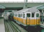 Image 37156 (192k, 1024x667) Photo by: Steve Zabel Collection of: Joe Testagrose Location: City Square (Main Line El) |  Image 110640 (93k, 1024x812) Photo by: Richard Cheek/Historic American Engineering Record Collection of: Library of Congress, Prints and Photographs Division Location: Egleston (Main Line El) | 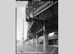 Image 110641 (102k, 812x1024) Photo by: Richard Cheek/Historic American Engineering Record Collection of: Library of Congress, Prints and Photographs Division Location: Egleston (Main Line El) |  Image 114386 (194k, 1024x689) Photo by: Steve Zabel Collection of: Joe Testagrose Location: Egleston (Main Line El) |
Photos by Location
Photo locations: Everett (Main Line El), Sullivan Square (Main Line El), Thompson Square (Main Line El), City Square (Main Line El), Charles River Bridge (Main Line El), North Station (Main Line El), Washington Street Tunnel Portal (Main Line El), Mass Pike Bridge (Main Line El), Tower D - Location of Wye with Atlantic Ave. El (Main Line El), Between Tower D and Dover (Main Line El), Dover (Main Line El), Between Dover and Northampton (Main Line El), Northampton (Main Line El), Between Northampton and Dudley (Main Line El), Dudley (Main Line El), Between Dudley and Egleston (Main Line El), Egleston (Main Line El), Between Egleston and Green (Main Line El), Green (Main Line El), Between Green and Forest Hills (Main Line El), Forest Hills (Main Line El)