Chapter 10. Tunnels in City Streets
The New York Rapid Transit Railway Extensions · Engineering News, 1914
With the exception of the tunnels under the rivers, referred to in the next article, practically the only parts of the subway lines as now laid out, to be built as true tunnels, are those under Lexington Ave. for the two lower-level tracks from about 53rd St. to 78th St., and for all four tracks from about 91st St. to 102nd St. The total length of these four sections is about 2.6 miles, of which about 2 miles is to be built in tunnel. The tunnels on Sec. 9 are being driven in part by Messrs. Douglas & Shailer, under a subcontract for P. McGovern & Co. The rest are parts of Sec. 8, 10 and 11, and are being built by the Bradley Contracting Co.
No particularly new methods of driving these tunnels or of handling the material have been used, but some features of the work are of interest on account of the difficult and uncertain nature of the rock which has been encountered. This is the typical gneiss or mica schist which underlies the whole of Manhattan, varying from quite hard to very soft and partially disintegrated material, containing many seams and dipping and striking very irregularly, thus tending to cause slips and slides, which the utmost vigilance and care cannot always avoid. Driving a tunnel, therefore, or even making an open cut through this kind of material under a street carrying heavy city traffic, and with important buildings on both sides of it close to the work, requires most careful methods of excavation.
On Sec. 11, the situation is complicated by the change from double-deck two-track tunnels, one over the other, to a four-track section with all the tracks at one level, making a tunnel section of practically rectangular shape 16 ft. high and nearly 60 ft. wide (see Fig. (38-I).
A power plant which supplies air to all four of these sections was established by the Bradley Contracting Co., at 96th St. and the East River. It contains five compressors, each of a rated capacity of about 2100 cu.ft. of free air per min., which is piped through a 10-in. main to all sections, the distance from the power house to the center of the farthest section being about 2.5 miles. Comparatively little trouble has been experienced with this line, though, of course, with four separate and fairly large organizations depending on one source for their supply of air, there have been times occasionally when all would be working or attempting to work at full capacity and the pressure would consequently drop.
A supplementary compressor of about 1500-cu.ft. capacity, connected to an electric motor for use in emergencies, has been installed in a part of the completed subway on Sec. 9, at 77th-81st St., but so far it has not actually been used. There has been some trouble on the long main-feed lines with freezing in cold weather, but nothing of importance. The main is carried underneath the decking of the street.
The Bradley Contracting Co. arranged for the hauling and disposal of the muck from Sec. 9, as well as from all its own sections, so the same type of buckets are used throughout all four sections; they are the so called battleships already referred to (in the article on excavation).
In the tunnels, four small power shovels (Marion model 40) were used for handling the muck in as many headings, where there was room for them, but a great deal of the material was handled by hand shoveling. Some experiments were made with other types of mechanical excavators, designed for use in a more limited space than that necessary for the operation of a shovel, but they were not successful enough to warrant their continued use.
The buckets, placed on small four-wheel cars (Fig. 66, lower view), were hauled back and forth between the shafts and the headings by various means, but no mechanical locomotive power was used. Single-drum air hoisting machines were arranged on platforms above the floor of the tunnel to haul the cars up grade, either the loads out of the heading or the empties back as the case might be, the cars being allowed to coast down grade. A single haulage line was used, the end being carried back by hand or by a mule.
Where the rock was good the full section of double track was usually taken out by driving a top center heading about 8 ft. high and 12 ft. wide, keeping the enlargement close up. The heading was pulled by the usual V-shaped center cut, with necessary side rounds, 20 to 40 holes 6 to 8 ft. deep, according to the character of the rock, being required for the whole heading. About 3 lb. of 60% forcite was required per cu.yd. in the headings in hard rock; 40% was used in the softer rock.
In one case a pilot heading was first driven all the way through between two of the shafts to permit better ventilation, especially for the erection of the structure, which it was desired to keep fairly close up to the excavation.
Timbering was required to support the rock in many places, and although segmental timbering was used, the arch was so flat that some center supports were almost always required. The original design for the double-track tunnels provided for a reinforced-concrete center wall, but here as in the use of this class of material in the cut-and-cover sections, where the ground or the street surface required continuous support, it was found to be difficult to make a good job with it. The type of structure shown in Fig. 9 permits the construction of the center wall with the two haunches, as shown in outline, before the rest of the structure is built and permits support on the permanent steel structure at once. The method is shown also in the sketch, Fig. 67, which shows the various steps of construction in the double deck, double-track tunnels on Sec. 11 and also incidentally the enlargement for the upper level local station at 96th St.
Figs. 69 and 70 show typical methods of supporting the timbering and the rock above, where the latter was generally fairly good. The methods used varied in detail in different headings, but in general were more or less alike. The flatness of the arch will be noted and the supports on either side of the center wall, permitting the construction of this latter and the transference to it of the load, thus permitting the construction of the two arches.

Views In Lexington Ave. Tunnel. Segmental roof timbering.
Near the upper end of Sec. 8 and 9, from 56th to 78th St., very soft disintegrated rock, carrying considerable water, was found, necessitating typical soft-ground tunneling methods. Timbered side drifts were driven for the wall plates, segmental timbering tightly lagged was erected from them with about twelve inches between each ring, crown bars and poling boards were used, but the latter were not usually driven, as the rock would hold for a short time. The method actually used was really to place lagging over the top of the arch in the position of poling boards, wedged down at one end, over the last ring erected, in the position in which poling boards would usually be driven. These projected forward over the position of the next ring and were blocked up from it after it was erected. This slight variation from the method of placing the lagging provided some protection from small dropping rocks, and was more easily accomplished than driving the poling boards, which would have been difficult in the material excavated.
The general appearance of this timber section is shown in the upper left view in Fig. 66, but in some parts of the work where the ground was particularly heavy, the space between the timber rings was filled with concrete as soon as possible after they were erected, and the ground overhead was thoroughly grouted. Even then it was necessary to use some temporary supports for the center. Details of two types of timbering used are shown in Figs. 69 and 70.
As is indicated in this latter drawing, the wall plates were sometimes supported on a ledge of rock, but more often were posted down to subgrade when the bench was excavated. The raking braces shown were usually only used temporarily to help support the wall plate while the posts were set under ill very soft material, but occasionally they were left in.
Fig. 71 shows a method of timbering used as part of Sec. 9 south of 78th St., where the rock, while quite hard, required support to prevent slides or the possible movement of large masses. A center top heading was driven and as soon as the enlargement was made, which was kept close up, the timber was erected, as shown in the "first stage" cross-section. In the "second stage" the two pairs of continuous I-beams are placed to span the bench excavation as shown in the longitudinal section in Fig. 70. These I-beams were joined with long splices to develop full strength at the joints and were made continuous throughout the work. The muck from the heading and enlargement was brought out in small buckets on the tracks, laid on the cross-braces at the springing line and dumped into the buckets on the tracks below, at a point back of the face of the bench.
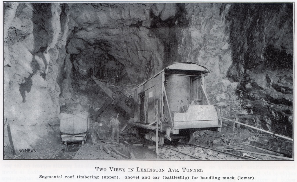
Views In Lexington Ave. Tunnel. Shovel and car (battleship) for handling muck.
All timber is provided and placed by the contractor at his own expense, the cost being included in the excavation price. The extra excavation necessary to place the timbers outside the lines of the structure is also at the contractor's expense, the payment line being confined to the neat line of the structure. Concrete placed between the timbers, however, is paid for where ordered, as is also the grouting.
At some places a center top heading was driven ahead, then the enlargement was made all on one side just large enough to permit the steel and concrete structure for one track to be built in it, then the further enlargement was made for the second tunnel, the top of the center wall forming the abutment for the arch first erected being necessarily braced to the sides until the second arch was erected. This method obviated the necessity of anything but occasional support of the rock where there appeared to be a tendency to slip.
On Sec. 8 and 9, the cut-and-cover excavation for the upper-level tracks was quite generally completed and the structure erected in it before the tunnel underneath was driven. No damage to the upper structure or difficulty of moment has been experienced due to this method of procedure except in one or two cases, where the extremely heavy rains of last fall, working under the completed upper structure, washed some of the material under it, into the excavation of the tunnel below, the heading of which happened at that time to be in very soft disintegrated rock. The upper tunnel structure at this point was temporarily supported by heavy timbers and girders which spanned the washed-out portion and the latter was then thoroughly grouted and the trouble remedied. Close watch was kept at all times of the upper tunnel at points just above the places where work was being carried on below, and any indications of trouble, as were shown in one or two cases by small cracks, were investigated and the ground below thoroughly grouted if this appeared necessary. The efficiency of this grouting under high pressure was shown in one case where grouting was done from below, the grout being forced up into the upper tunnel.
Just north of 98th St., the two upper tunnels spread out, and as soon as they get far enough apart, drop down to the level of the lower tunnels, until all four are at the same grade, as shown in Fig. 68 (I). Working from the shaft at 97th St. toward the north, the two lower tunnels are being driven first and the steel and concrete structure erected in them, then the two upper tunnels are to be driven at the sides. The cross-section (C) will show the necessity of this, as it will easily be seen that the corners (X) and (Y) will probably break through, and the character of the rock is such that it would hardly be possible to hold up the mass between.
At the upper end of this section at 102nd St., working southerly in the four-track section (Fig. 68), the method which has been developed and started is based on the idea of driving one side of the tunnel first for a distance of about 80 ft., then erecting the structure in it, then starting the second tunnel, and so on, thereby avoiding having the excavation open for more than the width of one tunnel at once.
Some difficulty was experienced in catching up some of the portals, a typical method of overcoming it being shown in the sketch. Fig. 68 (II). At the beginning of the double-deck tunnel just south of 95th St., the lower level was driven through, the steel structure erected and concreted, then the upper level was worked back from the inside to the portal, as shown.
At the portal at 102nd St., where the four tracks are all at one level, a side drift was driven for a length of almost 80 ft., a crosscut was then made from this drift the full width of the structure, as shown in the sketch, Fig. 68 (III), and the structure then erected so that the rock was caught up and then the excavation carried back out to the portal.
Vesey St. Iron-Lined Tunnels. On Sec. 1-A of the Broadway line there is a reversed curve where the route passes from Church St. through Vesey St. to Broadway, and the narrowness of the streets makes it necessary to pass under private property at each of the corners. The material for a considerable depth (50 to 60 ft.) below the streets in this section is sand, hut it is comparatively dry down to the level of the bottom of the subway structure, which latter is about 4 ft. below mean high water.
Easements were obtained under the two pieces of private property referred to, namely, the Trinity Parish House and the old Astor Hotel, on condition that the former should be properly supported on new foundations, bridged over the tunnel, and that on the site of the latter (which was razed) suitable foundations for the heaviest type of building should be provided, also, of course, bridged over the tunnel where this passed through them. Under these conditions it was thought desirable to design two separate circular cast-iron lined tunnels or tubes. The two tubes together have a length of about 1200 ft. and will require about 4350 tons of cast iron for the lining and about 17,000 cu.yd. of concrete.
As these sections of iron-lined tunnel are comparatively short, the use of the usual type of pneumatic shield for driving them would have involved a somewhat high cost for plant, chargeable to only a small amount of work. Besides this, the driving of tunnels by the shield method on curves of as small radius as this is a somewhat difficult operation, though on the Hudson & Manhattan R.R. there is at the corner of Morton and Greenwich St. a curve of 150-ft. radius, which was successfully driven by the use of the shield. The diameter of these tunnels was, however, some 3.5 ft. less than those at Vesey St.
The contractors, Messrs. F. L. Crawford, Inc., adopted therefore, for this work, a method developed by them and their engineer, J. C. Meem, Member, American Society of Civil Engineers, some years ago in the construction of some large circular brick trunk sewers in Brooklyn and which was quite fully described in a paper presented by Mr. Meem to the Brooklyn Engineers' Club in May, 1905.

Fig. 73. Views in Vesey St. tunnel. (1) Temporary bracing and lagging. (2) Iron-lined tunnel and pilot girder. (3) Segmental roof shields-jills. (4) Tunnel and pilot girder, erector.
This method as modified for the construction of these tunnels is shown quite clearly in the drawings and photographs, Figs. 73 and 74. A top heading is driven, the roof protection being afforded by the five sectional shields or jills, a detail of which is shown in Fig. 74 (D), and the front end in the photograph, Fig. 73 (1). These are shoved ahead by hydraulic jacks, and a lining of 2-in. hardwood lagging put in behind them, under the tail; this is temporarily supported by crown bars and blocking, which in turn are supported by segmental timbers consisting of the cap made of a 16x12-in. cut on top to chords of the curve and flat underneath to take the posts, and the two side pieces, as shown in the drawing, Fig. 74, (a) and (b). and the photograph, Fig. 73 (3).

Fig. 67. Diagrams showing method of roof support from center partition wall, section II route 5, Lexington Ave. Fig. 68. Transition from double deck to four tracks; method of catching up portal; method of catching up portal at 102nd St. Fig. 69. Timbering methods. Section 8, Lexington Ave. tunnel. Fig. 70. Timbering method, Section 9, Lexington Ave. tunnel (X&Y). Fig. 71. Sketches showing timbering supports, etc. Section 9. Fig. 72. Cross-section and part elevation of Vesey St. cast-iron lined tunnel. Fig. 74. Sketches showing Meem's method of tunneling, Vesey Street Tunnel. (Click image to enlarge.)
From the heading, the sides are worked down to about the springing line (horizontal diameter) by placing the 5-ft. lengths of horizontal lagging much as it is placed in the pits for underpinning and as shown in the photograph. Fig. 73 (3). To get out the excavation in the center below the heading, the top cap is carried temporarily on the 20-in. I-beams shown in Fig. 74 (a), spanning the working space from the erected intermediate sill (the one just above the center of the circle) to the firm ground in the bottom of the heading.
This permits the advancement of the so called pilot girder, which is advanced along the center in the position of the pilot tunnel of the old Anderson & Barr method. The girder in the present instance, however, only serves a purpose similar to that of the temporary I-beams above, that of supporting the overhead structure of timber blocking, over the working space, its rear end being supported on blocking from the erected iron lining, its front end on the unexcavated ground of the second lift just below the center. The photographs, Fig. 73 (2) and (4), show the method of using the erector around the pilot girder, and the latter part of the tunnel under the Trinity Parish House, which had previously been underpinned and the space above the tunnel bridged over.
The girder itself is made up in 12-ft. sections arranged so that the rear section can be detached and bolted on to the front, overlapping about 3 ft. Extra holes are provided so that the progress can be made either in a straight line or deflected to fit the curvature. The girder flanges are 8x8x0.5 in. angles, and the latticing 4x4x0.5-in. angles. The girders are 3 ft. on centers held together and braced by 4x0.75-in. bars. The roof load of the tunnel, which the girder supports, is estimated to be about 10 tons per lin.ft., but the girders are designed to carry a maximum load of 40 tons per lin.ft. for spans of 12 ft., thus providing for uncertainty and probable irregularity of loading and support.
The hardwood lagging is left in place when the cast-iron lining is erected. The latter weighs approximately 6600 lb. per lin.ft. of tunnel and it is cast in the usual segmental form. The individual segments are 6 ft. 2 in. long, 20 in. wide and weigh about 1500 lb. each. Every fifth ring is a taper ring for the curves, other taper rings (with considerably less taper) are provided for correcting the alignment when this becomes necessary.
In making the excavation the ground at the breasts, as well as the sides, is usually held at all points by lagging or poling bounds to prevent any subsidence or flow of material.
The Harlem River tunnels, the East River tunnels and the crossing of the Lexington Ave. subway under the New York Central R.R. tracks will be described in the next issue.