The New Coney Island Shops
The New Coney Island Shops
B.M.T. Monthly · Special Edition, 1926
The new Coney Island Shops for the maintenance of rapid transit equipment are located between the Sea Beach and Culver Lines and extend from Avenue X south to Coney Island creek. Connections are provided to the Culver, Sea Beach and West End lines and through the Coney Island terminal to the Brighton Beach Line.
The new shops replace the former inadequate shops located at 39th Street, and East New York. They are designed to maintain 2000 subway cars in service and liberal provision is made for the expansion of each department to meet the future demands. Development of the plans was begun in September 1923. The preliminary plans were developed by the transit company with the assistance of the engineering firm of Dwight P. Robinson & Co. The preliminary plans were turned over to the Board of Transportation where the building plans and contracts were prepared under the direction of Mr. Robert Ridgway, Chief Engineer. The equipment plans and specifications, including selection of machines, were made by the transit company. The buildings comprise the Inspection Shed, Main Repair Shop, two-story Store House, Oil House, Boiler House, Office Building and Electrical Repair Shop. They have a total floor area of 546,000 square feet, or about 13 acres; the approximate cost of the entire plant as provided by the City of New York and including the contribution of the transit company, under the so-called Dual Subway contract is estimated in the first instance to approximate $12,000,000, but when all extensions have been provided for, the ultimate cost will be considerably greater.
The building site is on the old marsh along Coney Island creek. Most of this area was filled with subway excavation to a depth of 7 feet to 12 feet, a number of years ago, The settlement of this fill had displaced the underlying mud in many places and had formed mud waves which made an unsatisfactory foundation condition for the buildings and equipment. Before construction commenced, the site was graded, the surcharge being moved into the low and unfilled portions. Concrete piles were then driven for the support of the building structure. The concrete piles, which were driven in groups under the building columns were tied together by reinforced concrete beams which form the supports for the building walls. In some places where mud waves existed under the new fill it was found necessary to drive concrete piles for the support of shop floors. In general, the floor, which was placed on the fill after the site bad been graded, consisted of an 8 or 9-inch concrete slab heavily reinforced, top and bottom with rods in each direction. It was also planned to have this floor slab support the machine tools and other equipment with the exception of the heavier units which required pits and where cushions were required under hammer foundations. Under the wheel lathe, air compressors and similar equipment, wood piles were driven under the concrete foundations, the piles being cut off with the tops in ground water.
The building construction consists of complete structural steel frames with brick walls, steel sash, concrete roof slabs covered with five-ply roofing. The buildings have large side wall sash and the roof, which is flat, consists of alternate high and low panels supported on the bottom and top chords of the roof trusses. At each truss there is a continuous line of top hung sash inclined at an angle of approximately 27 degrees to the vertical thus distributing ample natural illumination to all parts of the buildings. The overhead sash, skylights, and movable ventilating sections of the side wall sash are glazed with 1/4-inch wire glass, other side wall sash is glazed with 1/4-inch rough glass. All ventilating sections of windows and skylights are arranged to be operated from the floor. Interior doors are of the Kalamein construction. Track doors are rolling steel shutters and where these doors will be subjected to frequent operation, they are electrically operated with push button control. In general, wood block flooring is used throughout the shop; in the Schedule Car Repair Shop, wood mill and on the mezzanine, the flooring consists of 2 1/2-inch "Blox-on-end" flooring; in the Machine Shop, Truck Shop, Transfer Bay and similar places where traffic and wear will be heavy, 2 1/2-inch creosoted wood block is used. The flooring in the Wash and Locker Room, Inspection Shed, Store House, Toilet Rooms, etc., are cement finished with sanitary coved base. A system of pipe trenches built into the floor slab provide space for the air, oil and gas mains also for the return piping of the heating system. The interior of the shop is painted throughout; the side walls and ceilings are painted white with a gray tint. Black dados about 5 feet high are painted on walls, columns, etc. The effect of this painting is to reflect and diffuse the light in all parts of the shop.
The Electrical Repair Shop was the first building to be constructed as it was needed to replace the old shop at 52nd Street. This new shop was put into service in January, 1926. This building is devoted to the repair of armatures, controllers and passimeters. All coil work is done in this building and a laboratory for testing purposes is provided. The building is 127 feet wide by approximately 300 feet long consisting of a high central bay 64 feet wide with overhead cranes and side bays with mezzanines for coil winding, dipping and baking rooms, etc. Special attention has been paid to the natural lighting in this building. The mezzanines and space under them are well lighted by large windows in the side walls and the central bay is covered by a saw-tooth roof with additional roof lights consisting of large tile with insert glass. The need of this excellent natural light is apparent when it is noted that all of the armature stripping, winding and banding is done in this central bay.
The other main buildings were placed under contract at a later date than the Electrical Repair Shop and are now completed and in service. The Inspection Shed on the west side of the group is connected at the north end to the Sea Beach Line and at the south end to the yard. The building, 86 feet wide by 600 feet long, has four tracks with pits, bench space and storage room. This building provides for the inspection of trains from the Brighton Beach, Sea Beach, Fourth Avenue and West End Lines. Cars leaving the Repair Shop will also pass through the Inspection Shed for final inspection and adjustment of brake rigging, etc., before entering service.
The west side of the Main Shop building, known as the Intermediate Repair Shop, will be used for truck and running repairs. This building is 80 feet wide by by 480 feet long with two tracks connected to the yard at each end. Each track will be equipped with a drop type transfer table by which damaged trucks can be removed and good order trucks replaced under cars. During this operation the car body will be held up by special overhead cranes equipped with suspension hooks which will engage the underside of the car sills. The central bay of this building, 43 feet wide, will be used for truck overhauling and repairs and is equipped with two 15-ton cranes.
The south end of the Main Building is one large room 255 feet long and 520 feet wide. It is divided into three 75-foot bays extending east and west with 10-foot trucking aisles between the same. Each 75-foot bay is served by a 30-ton overhead crane equipped with two 15-ton trolleys. Each trolley is equipped with removable hooks by which car bodies can be lifted off trucks and spotted for repairs or painting, the crane lift of 30 feet being sufficient to transport car bodies over other cars standing on the floor. The tracks in this building are 20 feet apart allowing ample working and trucking space between cars. The track along the west wall is assigned for high tension test purposes. The testing unit is located on a platform above the track. Adjacent to this track and occupying the west end of the building are nine tracks, or space for 27 cars, provided for repairs to damaged cars and for car construction work. The central part of the room is assigned for scheduled car overhauling. For this purpose the cars enter the shop from the south on the stripping track, the car bodies are then removed from the trucks by the overhead cranes and placed upon specially designed steel horses which are high enough to permit ready access to the equipment under the car body and without the use of pits. The trucks then continue through on the stripping track to the truck shop in the north end for overhauling. Seats and equipment parts are removed from the car body and transported by storage battery trucks to the appropriate departments for repairs. After the car body repairs have been made it is then moved by the overhead crane to the east end of the building where it is painted, then again by crane to the wheeling and trim tracks where it is placed on the trucks coming out of the Truck Repair Shop. There is space for 18 car bodies in the Scheduled Car Repair Section and an equal space in the Paint Section.
In order to keep the shop as clean as possible, cars before entering the repair shop are cleaned in the cleaning room at the southeast corner of the building.
As this shop is essentially a steel car Repair Shop, the Wood Mill and Carpenter Shop are of minor importance as compared with the usual Repair Shop. This work is accommodated in a one-story building 40 feet by 230 feet, directly east of and connected to the Paint Shop and Transfer Bay.
The north end of the building is devoted to truck overhauling, machine and blacksmith work and miscellaneous repair. Between these departments and the Scheduled Car Repair Shop there is a Cross Transfer Bay, 40 feet wide and 640 feet long, served with two 15-ton cranes at a height of 30 feet. This Transfer Bay furnishes cross movement and direct access to every department of the Shop. The cranes north of the Transfer Bay are at a lower level and extend into the Transfer Bay for ready exchange of loads from one crane to the other. Between the Transfer Bay and the Scheduled Car Repair Shop is an area 60 feet wide by 560 feet long with a mezzanine floor 40 feet wide above. On the ground floor are located rigging, sheet metal work, electrical construction work, pipe-fitting and shoe beam work, these departments thus being located close to the car repair work. Storage of parts and supplies are also located in this section. On the mezzanine floor above are the curtain and sign work and seat cleaning and repairs.
The following departments are located in the north end of the building:
- Wheel and Axle Shop, 60 feet by 200 feet with 7 1/2-ton crane.
- Storage Yard, 60 feet by 200 feet with 7 1/2-ton crane and covered storage 20 feet by 100 feet.
- Blacksmith Shop, 80 feet by 200 feet with one 5-ton crane and jib cranes.
- Truck Overhauling, Cleaning and Painting, 120 feet by 200 feet, with one 15-ton and nine 5-ton cranes.
- Truck Assembly, 60 feet by 200 feet, with 15 ton crane.
- Machine Shop and Tool Room, 60 feet by 200 feet, with one 5-ton crane.
- Air Brake Department, 40 feet by 200 feet, with one 2-ton crane.
The northeast corner of the building which is nearest the entrance provides accommodations for employees consisting of a Wash and Locker Room on the ground floor and a half mezzanine. This room is equipped with 32 circular Bradley wash fountains each capable of accommodating eight to ten men at one time. Space is also provided for 1000 of the transit company's standard metal clothes lockers, which are 12 inches by 15 inches by 6 feet high. Directly south of the Wash and Locker Room a First-Aid room is provided which is equipped with the usual First-Aid Room facilities. The upper floor over the Wash and Locker room, 60 feet by 200 feet, and which is on the same level as the Shop Mezzanine, is allocated for Lunch Room and recreation purposes. Toilet facilities are provided in rooms on the mezzanine with direct stairway access from the main floor. Isolated toilet facilities are provided at frequent and convenient locations on the main floor throughout the shop. Drinking fountains are also provided at convenient locations throughout the shop. These fountains have all ice chamber with coil, thus providing cool water to employees.
East of the Main Shop there is a two-story fire proof Store House, 60 feet by 300 feet, and designed for a future third story. The second story is connected to the Main Shop by a bridge on the Mezzanine level by which truck loads of material can pass through the mezzanine of the Main Shop and over a second bridge into the Inspection Shed. Elevators of 10,000 pounds capacity are provided in the Store House, Main Shop and Inspection Shed. The elevators have 8 feet by 12 feet platforms and a speed of 75 feet per minute. The control is of the push button type thus dispelling with need of operators.
East of the Store House are located the Oil House and Office Building. The Oil House is a one-story and basement building, the basement being devoted to tank storage of lubricating oils with space for waste, etc. An elevator handles material to and from the basement. The main floor is occupied by oil pumps, barrel racks with tiering machine, etc. Part of this floor also is used for the renovation of waste, the treatment of journal box packing, and paint and paint brush storage. The distribution of the lubricating oils to this large plant has been given special study and the Bowser system used throughout. Oils are received in tank car shipments, unloaded through fill pipes to tanks in the basement and then pumped by motor driven pumps to various stations throughout the shop where the oil must be drawn for use. At each of these stations are located 120-gallon tanks with hand pumps for drawing oil. The supply of oil from the Oil House to these small tanks is controlled by remote control valves at each tank. When necessary to replenish the supply of oil in a distribution tank the operator opens the remote control valve which automatically starts the oil pump in the Oil House. Oils that are used in small quantities are transported in drums or portable tanks on storage battery trucks.
The Office Building is fireproof, 50 feet by 110 feet, two stories in height and planned for a future third story. This is located close to the entrance gates and now houses the offices and drafting room of the Mechanical Department. Two vaults are provided for storing drawings and records. An entrance gate house at the yard entrance is also provided at which there is stationed a watchman, a waiting room and employment office.
Heating is provided from a central heating plant located in a separate building, the equipment consisting of two 400 HP Heine water tube boilers equipped with Bethlehem-Dahl oil burners and capable of operating at 200% of rating. Space is also provided for two additional boilers. Sea grade fuel oil is used and storage is provided in three 8500-gallon tanks buried in the yard. The boilers are connected through overhead flues to an 8 foot by 200 foot radial brick stack. Steam is generated at 160 pound pressure and distributed at this pressure through mains to pressure reducing valves where the pressure is reduced to 3 pounds. The shops are heated by 71 unit heaters containing heating coils and electrically driven fans. In general, air is drawn in to the heater near the floor and blown out above head height at a temperature of about 120 degrees. The locations of the heaters and the direction of the blasts are such that the warm air is distributed to all parts of the shop. Offices, toilet rooms and other small enclosures are heated by direct radiation. The heating system is operated on the vacuum principle, condensation being collected by five vacuum pumps which return the condensate to the feed water heater in the Boiler House.
The regular 600 volt D.C. railway current, furnished through a separate feeder from the Avenue U sub-station, is used for light and power. The feeders enter through underground ducts to the switchboards, located in two fireproof switchboard rooms in the Transfer Bay. From these switchboards the current is distributed through separate feeders in underground conduits for lighting, crane operation, testing, and welding sets and machine tool power. Overhead lighting is provided of sufficient intensity to dispense with the use of individual tool lights. Plug outlets are provided on columns, walls, etc., for extension lights to be used in cars and for plugging into car lighting systems. In the Inspection Shop in addition to overhead lighting, pit lights are provided with enameled iron reflectors and so located as to illuminate the underside of the cars over the pits.
Two rooms are provided in the Transfer Bay for air compressors. The first installation consists of two 720 cubic feet electric driven Westinghouse air compressors with automatic control which maintains a pressure of 90 to 100 pounds at the receivers. Air distribution is provided to all parts of the shop through underground pipes in the pipe trenches and through branch pipes in the concrete floors to outlets in floors and on columns. Floor outlet boxes with hinged covers are set in the floor at frequent intervals where air hose connections can be made as required.
For shops covering so much ground as these, adequate handling and transportation facilities are of prime importance. This is provided for by 28 overhead electric traveling cranes located as previously mentioned. These cranes were built to the transit company's specifications by the Box Company and are arranged for cage or floor control depending upon the service required. In addition to the overhead cranes, the shop equipment includes a number of Ellwell-Parker storage battery trucks of various types for different services. These include, in addition to the standard trucks, special tractor cranes of 4000 to 6000 pounds capacity and Hi-Lo tractors for lifting and transporting loads on skids, etc. Dump bodies on skids and trailers will be provided for use with this equipment.
Although the buildings are either fire proof or of non-burnable construction and the shops are to be used for repairing steel cars, fire protection has been given consideration by the provision of an 8 inch water main looped around the shops and connected to the city mains. In addition to the yard hydrants, interior stand pipes with hose are provided throughout the Shop. In the Oil House there is also provided high pressure steam pipes with outside control valves for smothering fire inside of the building. Further consideration will be given to the necessity of sprinklers in the Wood Mill and Paint Shop where the risk may warrant their installation.
The Wheel and Axle Department
The Wheel and Axle Department the Coney Island Shops includes the heaviest and most expensive machinery in the plant. In this department wheels are bored, axles turned or straightened, defective wheels replaced and worn wheels are turned or replaced.
The shop equipment consists of:
- Heavy duty car wheel turning lathe.
- 400-ton hydraulic wheel press.
- 200-ton hydraulic axle straightening press.
- Two 40"x14" heavy duty gap lathes.
- Axle grinder.
- Two axle lathes.
- Two wet tool grinders.
The equipment was selected by the tool Committee after careful study of the various machines offered by the manufacturers. The latest improvements in machine tool design with automatic features are included, which insures good workmanship and low maintenance and labor costs. All machines are driven by direct connected electric motors using the 600-volt railway current.
The wheel lathe and the gap type journal truing lathe are located at the south end of the shop adjacent to the Transfer Bay, where mounted wheels coming from the Truck Shop and Intermediate Repair Shop are received. Three tracks are provided on which mounted wheels are stored as they move to and from the machines. Car loads of mounted wheels coming from the Inspection Shops and other points on the System will enter at the north end of the Shop where they will be unloaded and moved to the Storage tracks by the overhead cranes. Incoming mounted wheels which require journal truing will be set in the gap type journal truing lathe by the overhead jib crane on which there will be mounted a two-ton electric hoist. This jib crane will place the mounted wheels leaving the lathe on the track extending across the shop to the wheel lathe. At the intersection of this cross track with the storage tracks, special air lifts have been provided which act like a turntable for lifting and turning the wheels at right angles onto the storage tracks. These air lifts consist of an air cylinder below the floor and with saddles on the ends of the piston rods which engage the axles and form pivots on which the wheels can be easily swung around to the new position. Pressure of the operator's foot on a floor button operates the lift.
The wheel lathe which is made by the Sellers Company of Philadelphia, is the most expensive single piece of equipment in the entire plant. The machine sets in a pit on a heavy concrete foundation supported on piles. This machine which is of the most modern design will be operated by one operator with a helper who will be able to turn out three or more pairs of mounted wheels per hour. Operation throughout is largely automatic. The 50 h.p. driving motor is controlled with three push buttons which actuate switches in automatically correct sequence on a control switchboard. One push button starts the motor and brings it up to maximum speed. Another stops it by disconnecting the current and applying at the same time a powerful electric brake. If an especially hard spot on the wheels is encountered, a third push button at the operator's touch automatically slows down the machine.
Wheels are rolled into the machine and then centered by means of an air hoist attachment. The tailstock of the lathe is then moved forward by means of an 8 h.p. auxiliary motor to clamp the wheels in position and at the same time to adjust the driving dogs against the wheels and lock them in place. The auxiliary motor is controlled by a reversing controller which automatically locks the tailstock by an electric brake when the controller is turned back to the "off" position.
The tools are eight in number, of high grade cutting metal, and four are mounted ready for work in a turret in front of each wheel. When the roughing tool has finished its work the operator releases the tool and turns the turret so that the next finishing tool is in position for instantly commencing its work.
The car wheel borer is also made by the Sellers Company and will bore and face new wheels to fit the axles. The machine, which is driven by a 15 h.p. motor, is also equipped with two air hoists by which wheels are picked up and set in the machine. The use of the two cranes is a considerable time saver as it enables the operator to pick up one wheel while the machine is working upon another. A separate motor is provided for the rapid power traverse of the boring bar spindle and the machine is equipped with the Davis boring bar for roughing and finishing. A special side arm for facing and grooving is provided. This is of rigid construction with long bearing surfaces and gibs to take up wear. This attachment will face, turn and groove the hubs at the same time the wheel is being rough bored. There is a pan in a pit under the machine to catch chips. This pan when full can be removed by the crane.
There are two American gap lathes with double carriages which will true the journals with mounted wheels of 40 inches diameter. This machine has forced feed lubrication and can also be used as an engine lathe. The 400-ton wheel press made by the Chambersburg Engineering Co., is used for mounting and demounting wheels on axles. Through the use of the double head it is possible to either mount or remove one wheel, a gear and wheel or both wheels at the same operation.
A 20 h.p. motor drives a hydraulic pump which delivers a pressure of 400 tons to the rams. The pressure used in mounting wheels is recorded on a hydrauligraph, thus keeping a record of the pressures and insuring uniformity of work. The press is also equipped with compressed air by which the rams are quickly pulled back after the pressure stroke thus materially speeding up the work. A two-ton electric hoist on a jib crane is provided to serve the press. Wheels will be rolled into the press by hand.
The axle straightening press made by Watson and Stillman has a 5 h.p. motor driving a hydraulic pump which exerts a pressure on the ram of 200 tons for straightening axles. A special feature consists of a sliding carriage in which the axle is centered. The carriage can be shifted to apply pressure to any part of the axle. Springs lift the axle clear of the blocks for movement and a 1/4 h.p. motor rotates the axle to test its straightness. With these special features this machine can be operated by one man where two were formerly required.
A new feature of car maintenance work in the Metropolitan district is provided by the Landis Tool Company's axle grinding machine for grinding journals and armature shafts which insures better workmanship and reduces maintenance costs. This machine eliminates draw filing and burnishing of finished surfaces and reduces the time required to 30 minutes where 3 hours are required by older methods. The main shaft and most of the moving parts are enclosed thus adding to the safety of operation.
The shop equipment also includes special trucks for handling axles and storage battery trucks for transporting and towing the special axle trucks.
The building is 60 feet by 200 feet with equal yard space alongside the building for storage of wheels, axles, etc. Both shop and yard are served by overhead cranes of 7 1/2-tons capacity. The building is specially designed for the particular work to be done. There is excellent natural light from large windows and roof sash. All interior walls and ceiling are painted in light colors thus giving maximum diffusion of light. The flooring is of creosoted wood block on a concrete base which will resist wear from the wheels and other heavy loads.
The working conditions in this shop are of the best and in keeping with the high class of equipment which has been installed.
The Inspection Shop
A new activity has been added to the variety of enterprises that go on at Coney Island at night time. The new activity is an essential one so far as New York City is concerned, which is something that cannot be said of many of the activities at Coney Island. And it goes on winter and summer without regard to weather. The new activity is the inspection of subway cars for the Brighton Beach, Sea Beach, West End and Fourth Avenue Lines of the B.M.T. System. All of the subway cars operated on these lines are sent through the inspection shop at Coney Island on the average of once a week. And at the present time 60 per cent. of this car inspection work is done by the night force at Coney Island Inspection Shop.
At the present time the night force at Coney Island Inspection Shop inspects an average of 71 cars each night and in addition receives approximately 6 cars nightly from the intermediate repair shop to be prepared and inspected before being released for road service.
The inspection shop is located at the western end of the buildings that house the Coney Island Shops. It occupies a building 86 feet wide and 600 feet long in which are located four specially designed pits, each with a capacity for eight regular subway cars or four of the Triplex car units. Three of the pits are used at night for routine inspection work while the fourth is reserved for cars going to or coming from the intermediate Repair Shop or for cars which have been found on inspection to require special attention or repairs by the inspection shop force. By keeping one track in reserve for the work of an unusual character, the movement of cars over the inspection pits is maintained without unnecessary delay and thus a maximum number of cars can be handled by the inspection force.
By concentrating the inspection work on the subway cars for the southern division at Coney Island and doing the major part of the work there at night, it has been possible to develop the system of specialization of the work of individual workers to a greater degree than at any other inspection shop. This of course results in a greater proficiency at their special tasks by the individual workmen and also in increasing the output of the shop force as a whole.
The pits at the inspection shop are specially designed and one of the outstanding features of the pits is the provision for the safety and convenience of the men at work in them. The tracks at the pits are raised clear of the floor and mounted on cast steel chairs, so that there is a clear space of 9 inches between the floor and bottom of the rail. The pits are illuminated with special enameled white porcelain reflectors at frequent intervals, with the lamp sockets placed at the top of the reflector at an angle that will provide a maximum of light on the mechanism beneath the floor of the car. These light sockets have special cut-out switches and plugs that enable the workmen to cut out any individual light they desire and plug in their hand lamps when necessary without the bother of even removing the bulb from the pit socket. Alongside each pit is a metal enclosed cable with outlet receptacles approximately every 67 feet for use by the inspection force when they require power to test various parts of the electrical equipment of the cars on the pits. In addition to this power supply for test purposes there is a compressed air pipe line alongside each pit with cut-in valves approximately every 20 feet for use by the inspection force when testing the pneumatic portions of the car equipment or for cleaning purposes. At frequent intervals along the sides of the pits are toe-hold niches to enable workmen to get in and out of the pits without having to go to either end, where stairs are provided. To make it unnecessary for shop employees to jump pits when going from one side of the building to the other, cross planks with metal angles to keep them firmly in place are also provided at frequent intervals. For the use of men at work in the pits, short step ladders are kept in the pits so that there is no excuse for men standing on boxes or other makeshift ladders when their work requires them to get up close to the floors of the cars on the pits.
Along the easterly side of the Inspection Shop building are bench and rack facilities. There are 10 work benches of metal frame construction with wooden tops over which there is a sheet steel surface. Each bench is equipped with a vice, and has eight drawers for the storage of tools, materials, etc. There is one carpenter bench which is also of metal frame construction, but has no steel sheet over the wooden top. For the use of car body inspectors in preparing glass to replace windows, etc., in the cars as they go through the inspection shop, there is a specially designed glass cutting bench with the dimension lines carried across the entire top of the bench. There are also 13 tool cabinets for the use of the men employed at the shop. Each one of these cabinets has 12 drawers, each drawer with a separate lock, so that individual workmen may be assigned their own tool drawers in the cabinets. In addition, for the use of the workmen whose trade requires tool boxes, there are 4 cabinets designed to hold 30 tool boxes each. This also affords protection for the tool boxes and equipment owned by the individual employees. Other special equipment along this side of the shop includes 4 storage bins for glass with 12 compartments in each bin. All of the glass used in the inspection shop is stored in these bins so that it is quickly available for use when required. There is also a water rheostat and indicator board which is used to test the line switches on the subway cars. In addition, there is a lead-covered battery storage bench on which a reserve supply of batteries is kept after they have been delivered to the inspection shop from the Electrical Repair Shop. Another interesting feature of the equipment of the shop is the framed diagrams of the principal parts of equipment of the subway cars. These diagrams are distributed at frequent intervals along the shop walls so that they may be referred to readily by the workmen when occasion requires in the course of their inspection activities. There are also scattered about the shop 20 racks for the storage of shoe beams. Each rack has a capacity of 2 shoe beams. These racks help to keep the floor clear of large parts of equipment, such as shoe beams and thus reduces the hazards of accident due to careless placing of parts of the equipment on the floor. There is a storage cabinet for gasoline torches, each with a separate compartment for each torch.
The oil supply for use in the inspection shop is provided for by two stationary Bowser tanks of 115 gallons capacity each. These tanks are supplied directly from the storage tanks in the main oil house by means of pipe line connections. One of these tanks is used for compressor oil and the other for car oil. In addition, there are four portable Bowser oil tanks each with 65 gallons capacity. These are transported to and from the inspection shop on Hi-lo electric storage battery trucks which are used to great advantage throughout the entire series of shops, to handle the transporting and lifting of heavy supplies and equipment. These portable tanks contain denatured alcohol and the three varieties of oil used for lubricating special parts of the equipment.
There are two pulpit offices in the shop, each one of which has facilities for two sets of foremen. The foremen of the car body inspectors and the truck inspectors occupy one pulpit office, while the foremen of the electrical inspectors and the pneumatic inspectors occupy the other. Large receptacles are placed at intervals throughout the shop for the removal of rubbish. They are removed at regular intervals on Hi-lo trucks and empty ones provided, the loaded receptacles being transported to a central point for the disposal of waste and rubbish. Separate receptacles are provided for broken glass and also for scrap brake shoes. As the brake shoes are removed from the cars, the foremen indicate which are to be scrapped and which are to be saved, and those to be salvaged are collected separately so that there is no possibility of their being carried away with those to be scrapped. In addition to these large receptacles, smaller waste cans are placed at convenient locations throughout the shop and there is a regular schedule for the removal of rubbish from these cans. For use by the window cleaners, there is a storage bin for red sand which is used with pumice in the cleaning of the window and door glass of the subway cars. This combination of sand and pumice is used in damp form and is required to cut the grease which collects on the window and door glass of the rapid transit cars.
The inspection work itself is divided into four major classifications with a foreman supervising the work of each classification and the general foreman at the head of the entire shop organization. These four major classifications of inspection work are electrical, car body, truck and pneumatic. The inspectors in each classification take care of the inspection of that part of the car equipment as it goes through the shop. The work under each of the major classifications is further specialized, so that the electrical equipment, for instance, is subdivided into eight groups to each of which one inspector and his assistants devote their particular attention. The pneumatic equipment is likewise divided into six groups with special inspectors for each group.
As each car comes into the shop, four inspection cards are marked with its number, the date and the shop name. One of these cards lists alphabetically all the items of electrical equipment to be inspected, lubricated and tested; another lists the car body parts that must be inspected; the third the truck equipment items to be inspected and lubricated and the fourth the items of pneumatic equipment to be inspected, lubricated and tested. Each card is a distinctive color, green, blue, orange or pink. Each card has three columns, one in which the items are listed, the second for the signature of the inspector who has examined each item specified and the third for the signature of the assistant foreman who has checked the inspectors' work. The inspector certifies that he has "inspected this car and have left items opposite my signature in good condition for service". As a final check on the work, the foreman of each major classification signs each card for his class of work to indicate that he has examined the card and "believes this car is O.K. for operation". These cards are made part of the official shop records and provide an easy and accurate source of information as to who inspected any individual item of equipment on a car in the event that it becomes necessary to ascertain that fact. The individual signatures on the cards leave no possibilities of question on this score. After the cards leave the custody of the foremen and before they are filed each is checked by the office staff to make sure that there is individual certification as to the inspection and checking of each item of equipment and also the general certification by the foreman on every card.
To give an idea of the degree of specialization of work, the manner in which the electrical equipment is subdivided may be briefly outlined. One inspector will inspect and test the batteries. The second will inspect and lubricate the electric brakes and inspect the plug switches, "Power On" Recorder, relay and toggle switch. A third will take care of the inspection of the buzzers, switches, door operating boxes and incidental magnets, interlocks, signals, cutout and "Hubbell Plug". The fourth one devotes his attention to the inspection of contact shoes, and beams with the incidental fuses, shunts, fuse boxes, springs and leads. The fifth inspector specializes in coupler equipment: slides, fingers and shunts, together with the cable hangers and clamps and the junction boxes, jumpers receptacles and covers. To the sixth man falls the inspection of the electric trip switch and cable coupler, and the motors with their leads, brushes, brush holders and connectors; the lubrication of the automatic stop device, hangers and bolts and the trip switches; and also the testing of the main control circuits and the electric trip circuits. The compressor switch, main switch, resistance and leads, line switch with its fuse, resistance, overload trip and operating relay, together with the interlocks, magnets, switches and drums of the switch group are inspected by a seventh man, who also lubricates the overload trip and line breakers, the breaker, potential and accelerating relays, control cylinders and controller contacts. The eighth man inspects charging relays, fans, heaters, indicators, key switches, lights, markers and destination signs, master controllers with incidental resets, switches and advance switch, and the relays: E.M.F., control, door emergency light and resistances, as well as testing the door control circuits.
With the work of the various inspectors classified in this way it is possible for the shop to handle a large number of cars each night and the work of the various groups of inspectors is so planned that there is little or no interference between groups whose work is located in the same part of the car. Groups whose work might interfere because of a common location of the parts of the equipment to be inspected by the two groups usually start working from opposite ends of the pits so that they cross each others path but once while working on 24 cars.
A brief summary of some of the inspection work would be as follows: The truck inspectors examine the brake rigging, axles, wheels and brake shoes. If there are any adjustments of brake equipment required that make it necessary to send the truck into the Intermediate Repair Shop, the inspector notes this on the prescribed form and arranges to have the truck transferred to the other shop. So as not to withhold the car from service the usual procedure is to substitute an O.K. truck for the bad order one and the inspection force is required to prepare the bad order truck for delivery to the Intermediate Repair Shop and also make all connections on the substitute O.K. truck and approve the car with its new truck before it can be sent out on the road for passenger service. It usually requires from 45 to 50 minutes for this entire exchange of trucks.
This group also takes care of the lubrication of the truck and motor parts. The brake rigging and all movable parts oil the truck are lubricated every mileage inspection, about once a week for each subway car on the average. The waste on the journal boxes has to be inspected and a packing iron applied to make certain the waste is properly located under the journal seat. The oil in the armature and motor axle hearings is measured by a gauge provided for that purpose and the required amounts as indicated by the gauge are supplied. The packing used in the motor-axle bearings and journal bearings is removed and re-treated every 6 months.
To inspect the motors the covers are removed; the carbon brushes inspected for wear; the commutator, brushes and field leads examined as far as they can be observed to ascertain their condition, as well as the pole piece clearance. The surrounding parts of the armature and brush holders are examined to discover any accumulation of dust and compressed air is used to blow out the dust where necessary. The motor leads and motor lead connections are closely examined at this time. The contact shoe beams are given thorough inspections to determine their condition, and any needed adjustments of the suspension bolts are made. Attention is also given to the shoe fuses, terminals, flash boxes, contact shoe leads and jumpers, repairs and renewals made where necessary and the contact shoe then gauged and adjusted to the proper height.
The control equipment including the master controller and line switches, reverse and p.k. drums and contact switches, as well as the operating interlocks used in connection with these are inspected closely; the contacts replaced where necessary, any accumulation of dust removed and the parts lubricated. The operating magnet valves are tried out individually and as to final train operation from the master switch. The motor resistance is inspected as part of the control inspector's duties. Where it is found necessary to replace the resistances, these changes are most generally made by a repair crew, as a separate activity from the regular inspector's work. On the electrical portion of the Westinghouse H2A couplers, the couplers are dropped at the present time on every second mileage inspection, the slide contacts pads are removed, the contact fingers wiped off, and the interior of the housing cleaned out. The tension on the contact fingers is tried and the fingers gauged for proper height. The contact pad is inspected for wear on contact surfaces. Where necessary new pads for other parts are replaced at this time. After reassembly, the electric portion is tested for proper operation, as well as the automatic drawbar locking devices. On every inspection where the electric portion is not disassembled for inspection, the slide pad is pressed in so as to make an inspection of the contact fingers and where an unusual condition is observed, the housing is disassembled and the required adjustments made. The drawbar, automatic locking devices and equipment are tried out at this time, as well.
The men assigned to the above work also include in their activities the inspection of train line cables, jumpers and receptacles, as well as the hangers from which they are suspended. This work is done on every mileage inspection and where necessary the required adjustments or replacements are made.
The electrical automatic stop trips are tested on every inspection. The covers are removed, the electrical contacts and fingers inspected, the interiors wiped out and lightly lubricated. The trips are then reassembled and gauged for proper adjustments above the running rail and as to the proper centering of the trip arm after being applied. The action of the electro-pneumatic valve used in this circuit is tested as to its proper operation at this time. Where the adjustments or renewals are required on the trip equipment they are most generally made by the inspector who examines them.
The batteries are removed on every mileage inspection and refilled with the required amount of distilled water. The water used in the batteries is distilled in special stills, provided for this purpose in the Electrical Repair Shop. All of the vent caps on the batteries are cleaned of scale and then oiled, before being replaced in the battery boxes. The connections on each individual battery are also tried out to make sure they are tight after they have been replaced in the battery boxes, or cradles, after which the battery readings are taken to determine whether proper connections have been made and the batteries are in proper condition for service.
On the 2000 series subway cars which are equipped with door operating button boards, the covers are removed from the button boards in the master or operating car every mileage inspection. The buttons, carbons, contacts, key switch mechanism, door indicators, contact studs, terminals, leads, etc., are carefully inspected, adjusted, and necessary renewals or replacements made. After the board has been reassembled, the operation of the door circuits is tried out from the board. The outside emergency door push buttons, which are located on the outside of the car at the center side doors and bulkhead doors are removed, the contacts inspected and their interiors wiped off. After reassembly these are also tried out for proper operation.
The main panel board which includes the light, heat, fan, battery and compressor, switches and also the various fuses used in connection with these switches is examined on every mileage inspection, as well as the control and door operating circuits. The switches and circuits are tried out for proper operation, the fuses checked to insure that the proper size fuse is inserted in the proper fuse clips. All together there are 18 different size fuses used in this panel board. The key operated light ground switch is checked and tested as is also the emergency light relay. This inspector's duties also include the checking of the main car emergency and destination sign lights, and making the necessary replacements or repairs. The marker, tail and running lights are also tested by this inspector as well as the door signal lights. The outer surfaces of the door signal light lenses are cleaned at this time.
Tower A Controls Yard Moves At Coney Island Shops
Tower A, the first of the towers that will control car movements in and out of the Coney Island Shop Yards and the adjoining sections of main line tracks was placed in service on February 19th [1926]. The tower is equipped with the most modern devices and its 88 lever machine makes it one of the three largest towers in the system; only Tower No. 1 at East New York exceeding it in size and the Coney Island Creek Tower being on a par in size with Tower A. The new tower is a three-story brick structure standing about 300 yards northeast of the shop buildings and a short distance south of the 86th Street station of the Sea Beach Line. It controls the main line tracks of the Sea Beach Line between 86th Street and Coney Island Creek, the lead off tracks from the main line into the yard and eleven tracks in the yard. The switches and signals in this controlled territory are interlocked with the tower machine so that all train movements in this territory are regulated and governed by the towerman in charge at Tower A. Before this tower was placed in service, train and car movement on these yard tracks were controlled by handswitches and movements on the main line tracks and lead-offs into the yard were controlled from a temporary manually operated interlocking plant using semaphore signals. This method of control has now been abandoned.
The interlocking machine has a capacity for 88 positions in the frame but at the present time only 57 are in use. There are 22 switch levers, 25 home signal levers, 6 approach signal levers and 4 dwarf signal levers. The interlocking machine is the latest improved all-electric interlocking type and was built and installed by the General Railway Signal Company. The switches are operated from storage batteries.
On the new machine, the "call on" control, by which a towerman can instruct a motorman to key by a signal set against him if necessary, is located in the front of the machine. It consists of a button which when pressed flashes the "call on" indication at the signal. In the old type machines this "call on" control was in the back of the machine and the towerman bad to go behind the machine to operate a special lever to give the "call on" signal to the motorman. The new machine also has the ammeter and voltmeter on top of it in full view of the towerman so that be can tell at a glance just how the machine and switches are operating. With the old type machines, the ammeter and voltmeter are mounted on a switchboard located in various places about the tower so that the towerman could not read their indications in many cases without shifting from their posts in front of the machine. The new machine is provided with a combination polarized relay and circuit breaker on each switch machine lever so arranged that electrical trouble, such as a short circuit, in the control circuit for one switch unit will electrically disconnect the defective unit from the interlocking machine without interrupting the main current supply to other units as would happen with the old models of the machine.
The machine is installed in the top floor of the tower building. The second floor is equipped for the use of the towermen and maintainers while the ground floor is devoted to the storage of materials for use in the tower and entire interlocking plant it controls. Tower A eventually will be supplemented by another tower to be known as Tower B, in controlling car movements in and out of the vicinity of Coney Island Shop Yards.
The Blacksmith Shop
"Under a spreading chestnut tree- The village smithy stands"-Longfellow.
The forges and anvils in the Coney Island Shops are the only tools which link this plant with the "smithy" of our boyhood days and, in fact, carry the craft back to the days of Tubal Cain. Many of our readers remember some village shop and a brawny smith with bare arms and leather apron. What a fascination the smoky place with its creaking bellows, glowing fire, hot iron and clanking anvil had for the youngsters who gathered around the door to see the horses shod. The flivver has replaced the smithy with the service station, but forges will be used as long as metal must be worked.
In the Coney Island Shops, the forges are of the most modern design. The bellows are replaced with electric driven blowers and smoke is removed by an exhaust fan connected through underground ducts to hoods over the fires. There are 12 Buffalo down draft forges 3 1/2-feet to 4 feet square, with water boxes, fuel bins and electric driven blowers. Soft coal is used as fuel but the exhauster pulls the smoke away from the fires, leaving the air clear and fresh.
Forgings, which are too heavy for hand work, are handled on three air hammers, one of 1200 pounds capacity and two of 900 pounds each. Air at 90 pounds pressure from the shop compressors drive the hammers. The hammers rest on timbers supported on concrete foundations and separate cushioned foundations are provided under the anvil blocks.
Other large metal working tools include two Ajax Bulldozers, one of long stroke, slow speed for bending heavy work, the other of high speed short stroke and stop motion for light work. There is also a National forging machine for making bolts and rivets up to 1 1/2-inches in diameter. This machine is equipped with dies to forge bolts and rivets of various lengths and sizes. The operator feeds a hot bar into the machine and at each push on the foot pedal a completed rivet drops into the pit.
Furnaces are provided for serving the hammers, bulldozers and forging machine. Each furnace is specially selected for its particular service, some are single and some are double ended. There is also a double chamber tool furnace for tempering the special steels used in the shop tools; a pyrometer attached to this furnace records the furnace temperatures and insures the right working temperature for each kind of steel. Oil and water quenching tanks are used in this work.
A 72 x 96 inch car type annealing furnace and a 24 x 60 inch furnace are used for heat treating. Each furnace is equipped with recording pyrometer. The furnaces were made by the Mahr Manufacturing Company and each one has its own electric-driven blower.
Fuel oil is burned in all furnaces. It is stored in two 5,300 gallon underground tanks in the yard, whence it is pumped through underground pipes with branches, to each furnace.
Welding is an important item of repair work and in this shop both electric and gas welding is provided for. There are 12 brick-topped tables for gas welding and five stations for electric welding. Each of the latter is in a separate enclosure to protect other workmen from the glare of the welding arc.
Radial jib cranes are provided to serve the hammers and forges, and over the welding benches there is a five-ton floor-controlled electric traveling crane.
Bar and sheet iron, gas cylinders, etc., are stored in racks under a shed roof in the yard. When bar stock is brought into the shop it is cut to length in a powerful triple punch and shear which can also split plates. This machine has an unbreakable frame of armor plate and can shear 2 1/2-inch square bars or 6 x 6 inch angles. A high speed power hack saw is also used to cut bar stock.
Like all smith shops the floor is of cinders but trucking aisles of concrete have been provided. Unlike many smith shops the building has splendid natural light and ventilation from the roof skylights. Drinking fountains and shower baths will add to the comfort of the shop force, especially in hot weather. The smith shop is only one unit of the Coney Island Repair Shops, but with its high-class equipment and good working conditions it should give the other departments a hard run for the efficiency record of the shops.
The Machine and Air Brake Shops
The visitor to the Coney Island shops is attracted by the array of new tools in the machine shop. The machines are painted the B.M.T. machinery blue which contrasts strikingly with the polished metal surfaces and vivid red of the gear guards.
At the south end of the shop and near the transfer bay are two planers. The Gray planer is an open side machine 26 feet long with a table 12 feet long and four feet wide. This machine, which has two heads on the cross rail and one on the side housing, is driven by a 25 H. P. motor. The other planer, made by William Sellers, has a 36 inch by 8 foot table. There are two heads on the cross rail and the machine is driven by a 20 H. P. motor. Near the planer is located the Giddings Lewis horizontal double spindle, adjustable boring, milling and tapping machine. This machine has special attachments designed for the railroad company which permit both vertical and horizontal adjustments of the boring bars so that armature housing bearings and axle bearings in motor shells can be bored in one operation.
Near the center of the shop is the six-foot American Tool Works multiple duty radial drill and near by are located a group consisting of a two spindle bolt threading machines and five drills with single, double and triple spindles for light work. There are also two heavy duty swing drills, a 20 inch heavy duty shaper and a 12 inch slotting machine for cutting keyways, etc.
Along one side of the shop are located a Brown and Sharp milling machine, a group of four engine lathes, a Warner and Swazey heavy duty turret lathe and two screw machines.
There are two power hack saws for cutting bar stock; wet and dry tool grinders are also provided and placed at convenient locations.
There are fourteen 10 foot machinists' work benches of the new B.M.T. design. These are made of steel with tool drawers, vices, etc. All bins, lockers, racks, tool stands, etc., are also made of steel from B.M.T. designs.
A tool room, 20 feet by 40 feet and a tool crib 18 feet by 33 feet are located in the machine shop.
For handling materials the machine shop has a five-ton crane of 57 feet span and the air-brake shop has a two-ton crane of 18 feet span; the latter crane is controlled and operated from the floor. Materials are transported by storage battery trucks of the lift type. Materials and parts are placed in bins or stands with legs about 12 feet high. The storage battery truck runs its platform under the stand, lifts it up and transports the stand with its load where desired.
The tool room with its equipment is a complete machine shop in itself; the equipment comprises milling and shaping machines, cutters, tool and surface grinding machines, drills, lathes and drill pointer. The work done in the tool room consists of making and repairing tools for shop use and the work is enclosed by a heavy wire screen directly connected to the tool crib.
Much valuable material is stored in the tool crib whence it is issued on tool checks through serving windows on three sides of the room. The tool crib contains 35 steel bins, each 3 feet wide by 7 1/2-feet high for storage of tools and material for issue. The bins are arranged to form the room enclosure and heavy wire mesh forms a ceiling, preventing entrance to the room except through the, door or tool room.
The machine shop and its equipment does the machine work on repair parts for trucks, journal boxes, motor shells, draw bars, brake rigging, safety gates, parts of compressors. door engines, etc. These parts pass through the machine shop in small quantities requiring a shop which is quite different from a manufacturing plant where quantity production keeps each machine continuously engaged on one operation.
Next to the machine shop is the air brake shop where the air equipment is overhauled, repaired and tested. This equipment includes the car compressors, parts of door engines, brake valves, feed valves, compressor governors, triple valves, reservoir tanks, air hose and many similar minor parts.
The work is practically all bench work as the machine work goes to the machine shop.
The reservoir tanks are scraped, tested to 150 pounds pressure, and painted. Compressor armatures are removed and the compressors cleaned in potash and water tanks before repairs. Oil removed from incoming compressors is reclaimed and stored for use. At the north end of the shop are the benches for valve repairs with compressor and separate testing racks for each type of valve. The air brake shop makes the periodic overhaul of 1,100 car compressors, portions of 14,000 door engines, and valves and other parts in proportion. Safe working brakes on the subway cars and smooth, quick acting doors are the result of the skilled work in this department.
The Mechanical Department's New Supply Car, No. 5003
Supply car No. 5003, used by the Mechanical Department to transport materials to and from the various shops about the B.M.T. System made its first run over the elevated and subway lines on Monday, February 6th. The car, one of the most modern of its kind, is equipped with a two-ton circular crane that facilitates the loading and unloading of the car. The car is housed at the Coney Island Shops and makes that shop its focal point in the distribution of materials to the various shops of the System. The car itself is different in appearance than anything that has been seen on the Company's lines. It has the appearance of a U. S. mail car with sliding double doors on either side. It is painted red and on the sides is lettered the symbol of the B.M.T. Lines in colors. Over all it measures 48 feet 3 inches and is 8 feet 7 inches wide. The car body itself is 37 feet 6 inches long with open platforms, on which guard rails are mounted, at each end. Plenty of space is provided in the interior of the car for the storage of materials that are being transported between the Coney Island Shops and other shops of the system. About 72 square feet of open storage space is provided at one end of the car for large size material while the other end is occupied by steel lockers, suspended from the ceiling, for the handling of small size materials and materials handled in broken lots. Room is also provided for the storage of some materials under the lockers.
The center of the car houses the two-ton crane. The crane is one of the features of the new car. It is electrically operated. It easily lifts and lowers material that formerly had to be loaded and unloaded upon flat cars or in box cars by manual labor when transported from one shop to another. Now, one shopman in each shop is instructed in the operation of the crane and it is his task, on the arrival of the car, to operate it. The crane is circular and may be swung out either side of the car when the doors are open. An electrically operated extension may be projected from the arm if it is necessary and then drawn back inside the arm when the crane is ready to be swung back into the car. A switch near the motorman's cab controls the power for the operation of the crane so that it cannot be operated unless this switch is thrown in place. This is one of the many safety features governing the operation of the crane.
The car makes its run about the System on Mondays, Wednesdays and Fridays. Special motormen are assigned to its operation. This is necessary because of features in its control apparatus that are different from other subway or elevated cars. It is equipped with hand operated control that moves the car as soon as the controller is notched. Electric-pneumatic brakes stop the car similar to subway cars. The new car is also equipped with compromise type contact shoes that permit its operation over both the "L" and subway lines. The shoes are normally in the "down" position for operation over the subway third rail, and it is only necessary to raise the shoes and latch them in the "up" position for operation on the elevated lines, equipped with the third rail in the "old B.R.T." position.
Progressive Routing of Work Features New B.M.T. Shop.
Electric Railway Journal · Vol. 68, No. 25 · December 18, 1926 · pp 1080-1086.

The Central Bay of the B.M.T. Electrical Repair Shop and Four Departments in It. The four small pictures show close-ups in the corresponding corners of the bay, which is spanned by a 5-ton traveling crane and two traveling wall jib cranes.
The Electrical Repair Building Is the First of the New Coney Island Repair Shops to Be Used by the Rapid Transit Division of the Brooklyn-Manhattan Transit Corporation Ultra-Modern Equipment Installed for Making Repairs Quickly and Efficiently.
Carefully fitted out with the latest types of machine tools and other equipment needed for electrical repairs, the first unit of the new Coney Island repair shops of the Brooklyn-Manhattan Transit Corporation is in use. When completed the entire group will form the largest and best equipped electric railway inspection and repair shops in the world. Seven buildings are now in the course of erection, with a total floor area of nearly 13 acres. They comprise a main repair shop, an inspection shop, the electrical repair shop, which is the subject of this article; a two-story storehouse, a two-story office building, an oil house, and a boiler house. The total floor area of the seven buildings is 546,000 sq.ft.
The buildings themselves are being built by the city of New York under subway contract No. 4, while the railway company provides the equipment, including heating, lighting, power, machine tools, cranes, elevators, etc. The building now used for the department of electrical repairs is the first one to be completed and the city is now proceeding with the construction of the remainder of this comprehensive group of repair and inspection shops. The yards for these shops occupy the entire space between the Sea Beach and Culver lines of the railway at Avenue X and extend south to Coney Island Creek. The electrical repair shop occupies the northeast corner of this area immediately adjacent to the Avenue X station of the Culver line and but a short distance from the 86th Street station of the Sea Beach line. The shop building is 300 ft. long and 127 ft. wide. The central portion is open from floor to roof and a mezzanine floor 32 ft. wide extends along one side of the building with a space for a similar mezzanine to be built later on the opposite side. Particular attention has been devoted to providing large central sawtooth skylights and an unusual amount of wall space for windows so as to make the interior of the shop exceptionally light throughout the daylight hours and a most attractive place in which to work.
The framework of the electrical repair shop is of steel and the walls of tapestry brick with a concrete foundation. The building presents a very pleasing appearance with little attempt at ornamentation. The coping is of terra cotta and window sills are Rowlock brick. Windows are all fitted with steel sash. Ventilating panels in the exterior steel sash are glazed with 1/4-in. rough wire glass. Other glazing in the first story is 1/4-in. rough glass and the second story exterior steel sash is glazed with clear glass except in the ventilating panels. Roof lights are glazed with 1/4-in. rough wire glass. The roof over the center bay is of sawtooth design which furnishes abundance of interior light. The backs of the sawtooth section are of precast interlocking cement tile with glass inserts. The roof over the mezzanine floor and side bay is built of concrete slabs on steel with asphalt surfacing. The floor of the mezzanine section is of cement with an asphalt finish. The ground floor is of Carter Bloxonend flooring on a concrete base.
Unit heaters are located at intervals around the shop and wall radiators where required in rooms, etc. The heating system is of low-pressure type with vacuum return, steam at about 5 lb. pressure being used. Steam is now supplied from a temporary boiler, but as soon as the main boiler house is completed connection will be made to this.
All electric lighting fixtures are arranged to conform to the latest practice in shop lighting. The central bay is lighted from five-light clusters about 30 ft. above the floor and spaced on 20-ft. centers, each cluster consisting of five 94-watt lamps with porcelain reflectors. Side bays are supplied from single 94-watt lamps 10 ft. above the floor, with porcelain reflectors spaced on 8-ft. by 10-ft. centers. In the washroom and locker rooms 56-watt lamps are used. There are also separate circuits for watchmen's lights, fire apparatus, fire alarm and hydrant designation lights. The 600-volt direct-current system of the railway is used for lighting, five lamps being connected in series across the line.
All wire is run in conduit in the ceilings, floors and walls with pull boxes at convenient intervals. A general lighting and power switchboard is located on the south balcony of the shop. From this the circuits run to separate lighting and power panels at convenient points in the shop. These control panels are provided with Westinghouse safety switches mounted in steel cabinets with hinged doors.
Pipe trenches are provided for the distribution pipes for steam, air, gas, electricity and water. Pedestals are placed along each side of the central section of the shop devoted to stripping and winding of armatures. These pedestals include connections for gas, air at 90 lb. pressure and electricity at 110 volts a.c. and 600 volts d.c. Some further details as to the construction of these stands and the convenience for various classes of work will be given in connection with the shop equipment.
Electric railway maintenance men will find the new electrical repair shop of the Brooklyn-Manhattan Transit Corporation of particular interest because of the modern equipment provided. The shop is arranged to handle the largest as well as the smallest item of electrical repair work rapidly and efficiently. Quick repairs to electric car equipment are necessary, not only to keep the maximum number of cars in service continually, but also to minimize the number of spare parts that must be stocked.
In planning the department of electrical repairs, particular attention was given to grouping departments and equipment so that the part being repaired will move progressively from one operation to the next and all interference, cross-routing and back-tracking of parts will be eliminated. Provision for expansion and installation of equipment to meet future increased requirements has been made. Plenty of space has been left around machine tools so that equipment can be handled efficiently without interference. Speed in making repairs with an economical shop force has been sought. Quick movement of heavy parts is taken care of by a 5-ton Box traveling crane which spans the central bay and traverses its entire length, by two 1-1/2-ton Box traveling wall jib cranes, operated from the floor, and by several small storage-battery trucks. The wall jib cranes serve the machine tools so that the traveling crane can be used for longer movements and for placing material conveniently to machines.
An accompanying plan shows the shop divided into sections so as to illustrate the efficient manner in which work of similar character is grouped. A table lists the work done in each section. Lines with arrows show progressive movement of parts during repairs.
Section 3, with a track over which cars can be brought into the shop, is used for the receipt and shipping of all equipment and material. Armatures, the repair of which constitutes a large part of the work done at this shop, are inspected as they are received and are divided into two general classes first, those that require complete rewinding, and, second, those that can be repaired without rewinding. All armatures are moved into section 4 by cranes or trucks and are placed on adjustable stands manufactured by the Columbia Machine Works. These have a large steel bell-shaped base with roller-bearing cradles at the top. Two such stands support an armature. One is bolted securely to the floor, while the other is left free to be moved so that adjustment can be made to take care of various lengths. The head with the cradle has a screw bottom with square threads to provide a 10-in. height adjustment. A convenient height used for repair of armatures is with the roller bearings 36 in. above the floor level. In grouping the stands, the stationary ones are spaced 6 ft. apart. A winder's tool box and material stand of sheet steel is attached by hinged supports to the stationary armature stand. This is 15 in. wide, 18 in. long and 8 in. deep. It is provided with a sheet-steel drawer which can be locked. Space is provided in the armature repair section for a double row of winding stands on either side. But one row on each side is in use at the present time.
The armature rewinding and repair section is provided with twelve outlet pedestals. To these are brought pipes containing gas and compressed air and the conduit with wires for connection to both alternating and direct-current supply sources. Each pedestal has an upright circular steel base of 8 in. diameter and 29 in. high with a cast steel bottom. On top of the pedestal is mounted a square outlet box, 8 1/2 in. x 8 1/2 in. x 4 in. deep. The four sides are provided with proper fittings so that connection can be made quickly for gas, air, direct current and alternating current. Small brass plates on top of the cover indicate to the workman just which connection is to be used for each supply. There are six of these outlet pedestals, spaced 12 ft. apart, on each side of the armature rewinding and repair section.
Three soldering furnaces mounted permanently alongside the winding stands are used to heat irons for soldering the rear ends of some types of armature windings which cannot be dipped for soldering. Each soldering furnace has a gas connection and burner of sufficient size so that two soldering irons can be heated at one time. The furnaces are made by Charles A. Horn. They are mounted on a strap-iron stand which brings the furnace 2 ft. above the floor.
A Special Room For Cleaning. Armatures sent in for repairs usually need rebanding or new mica V-rings. Some single coils are replaced. If it is evident that an armature can be repaired without rewinding, it is sent to the cleaning room before dismantling. This room, shown as section 19 on the accompanying plan, is 19 ft. 6 in. x 14 ft. 9 in. and has two galvanized iron housings, 3 ft. x 3 ft. x 5 ft. long, into which the largest size railway armature as it rests on a truck can be rolled and be closed in completely during the cleaning operation.
Dust and grease caked solidly are loosened by scraping. Compressed air is played on the armature and a vacuum system sucks away all loose particles. The two receptacles are connected by 12-in. diameter pipes to a 16-in. diameter vertical pipe. The pipe from each receptacle has a damper so that one can be shut off while the other is in use. A hinged door the full size of the front of each receptacle is provided and to support the door as it is being opened a castor is fastened to the bottom corner farthest from the hinged side. The large front door is also provided with a small circular 15-in. door, and there is also a similar circular door in the opposite end of the receptacle. Another rectangular door 12 in. x 36 in. is provided in the side. These openings are for inserting the nozzle of an air hose to blow out the armatures. These cleaning receptacles are also used for cleaning numerous parts of electric car equipment, such as motor parts, controllers and the like.
Suction to remove the dust and loose particles is provided by a motor-driven fan mounted on the balcony, which serves as a roof for the cleaning room. The refuse material is drawn from the receptacles up through the vertical pipe to a Cyclone separator, in which large particles and any heavy material drop down and through an 8-in. pipe to a steel drum 24 in. diameter by 3 ft. high, which is placed in one corner of the cleaning room. The hood from the pipe fits over the top of the steel drum and is held in close contact by a large steel ring so that there is no tendency for the dirt to fly about the room. The top of the Cyclone separator is connected by a large pipe to a large dust chamber. Light particles are drawn through this and to the exhaust side of the fan, where they are blown outside the building.
After cleaning, armatures which are to be repaired are tested at 1,400 volts a.c. with a Westinghouse portable transformer box which is arranged to give testing voltages up to 6,000 in steps of 200. The box is brought to the armature to be tested.
Repairing And Rewinding Armatures. With all coils removed, the armature core is repaired. Any sharp corners or rough edges in the slots that might cause damage to the coils are filed and the slots are cleaned carefully to receive the insulating material for the core. The armatures are next moved to section 5 and the commutators are tested with 3,000 volts to ground and 550 volts between bars. Where repairs to the commutator are necessary these are made and the commutator is tightened carefully. Should there be short circuits or grounds inside or at the rear end which cannot be repaired properly with the commutator in place it is pressed off. This is done in section 8. A 200 - ton horizontal - hydraulic press made by the Hydraulic Press Manufacturing Company and a Watson-Stillman vertical press of 50 tons capacity do most of this work. A 60-ton horizontal hydraulic press is used for tightening collars, putting tension on commutators while the nuts are tightened and for removing pinions. These presses are also used for pressing shafts in and out and other forcing operations.
Repairs to commutators removed from the armatures are made in section 13. Unless a commutator is in very bad condition it is the practice to replace the same one on an armature. The armature under repairs is set aside meanwhile. With the commutator again in place, the armature is brought back to section 5 for rewinding.
To show the particular uses to which the various pieces of equipment are put in the department of electrical repairs would require a detailed description of each maintenance operation. The principal repairs made to an armature, however, will illustrate the need for much of the equipment. While armature repairs constitute a large part of the work done, the different steps in rewinding and the order in which the work is completed differ somewhat with the various types of armatures. For a large Westinghouse type 300 armature rewinding operations are as follows:
Armature Repair Work Outlined. The winder puts in the bottom coils and tapes them down to hold them in position, properly lined up. The armature is then placed in one of the baking ovens for two or three hours, in order to heat it up. Sticks are then put in on top of the coils and temporary bands are applied while the armature and coils are hot. After cooling, the armature is again placed on a stand in the winding section. The winder cuts the temporary bands and removes them, together with the sticks. Insulation is then inserted above the bottom coils and the top coils are placed in position. The armature then goes into the oven a second time for heating up and again sticks are placed over the coils and temporary bands force the coils down into position. When cold, the armature is again placed on stands and the temporary bands are cut and the sticks taken out. The winder then does the finishing work on the armature and it is given a buzzer test. The armature then goes to the solder pot for the dipping to solder the leads into the commutator neck. After a bar-to-bar test permanent bands are put on and the armature is again submitted to a buzzer test. If this latter test shows trouble in the winding, a bar-to-bar test is made to locate definitely the point of trouble.
The armature then goes into one of the lathes for turning and slotting the commutator. The slots are raked out and the commutator is polished. The armature then is sandpapered and another buzzer test is given it. The core of the armature is then painted and the tape band is given its final coat of varnish. A pinion key is put in the armature shaft and the pinion nut applied. The armature is then ready for service.
Drying And Baking Ovens Important Pieces Of Equipment. From the foregoing outline it will be seen that drying and baking ovens are used extensively. These are located in a separate room in section 11, adjacent to which is another room with a complete dipping and impregnating installation. At present six ovens have been installed and there is space for an additional one when the volume of work demands it. Five of the ovens are 10 ft. x 6 ft. 6 in. x 6 ft. high. Their floors are arranged to come flush with the shop floor so that trucks can be rolled-directly inside. A sixth oven is arranged for baking coils and small parts. It is 6 ft. x 5 ft. x 34 in. in size. The opening in this oven does not extend to the floor. This oven, together with four of the others, is of Gehnrich Indirect Heat Company's type. The sixth oven, formerly used at the railway's 52d Street shop, was made by the Oven Equipment & Manufacturing Company. The heating and control equipment for all of the ovens was furnished by the Westinghouse Electric & Manufacturing Company. The control boxes are installed on an angle iron framework along the wall of the oven room, directly in front of the ovens. A regulator, used in connection with an indicating and recording meter which is set for definite temperature limits, gives automatic heat control and eliminates the personal element.
The impregnating room has a mixing tank and an impregnating tank, supplied by the P. J. Devine Company, also equipment for dipping armatures by the rolling method and a very complete overhead I-beam hoist system for handling heavy pieces of equipment. Steam at 60-lb. pressure for heating the compound is furnished by a 4-hp. flash boiler made by P. M. Lattner Manufacturing Company. The mixing and vacuum tanks are jacketed for the steam. No pipes are in sight to become covered with compound and make cleaning difficult. The compound is heated in the mixing tank and a partial vacuum is obtained in the impregnating tank by means of air pumps. The equipment to be impregnated is then subjected to a 28-in. vacuum before the impregnating compound is admitted.
With the compound properly heated and mixed, the valve between the two tanks is opened and the compound runs into the impregnating tank. Peepholes in the top covers of these tanks permit the operator to watch the compound as it rises and shut off the valve when the equipment has been covered over to a depth of from 18 in. to 24 in. After closing the communicating valve the vacuum is relieved and air pressure is supplied by the shop air compressor at from 50 to 55 lb. Compressed air is also used in forcing the compound out of the impregnating tank and into the mixing tank, the maximum pressure used being not more than 5 lb. The vacuum tank used in this installation is 36 in. diameter by 56 in. deep. Both tanks are surrounded by an elevated platform so that workmen can reach all parts without difficulty.
Schedule of Work in Various Departments of B.M.T. Electrical Repair Shop. (Figures after section numbers are approximate areas).
- Section 1 3,480 Sq.Ft. For repairs to controller equipment, contactor boxes, switch groups, line switches, magnets and door equipment.
- Section 2 277 Sq.Ft. Control storeroom. Material necessary for repair parts made up in Section No. 1.
- Section 3 2,093 Sq.Ft. Shipping department.
- Section 4 1,798 Sq.Ft. Armature stripping department. Stripping of armatures. Rewinding and repair of coils.
- Section 5 3,306 Sq.Ft. Rewinding of heavy armatures. Soldering and banding of armatures previous to baking.
- Section 6 450 Sq.Ft. Soldering pots. All armature windings above 10 hp. are dipped.
- Section 7 1,944 Sq.Ft. Banding department. Armature banders. Armatures cleaned and slotted.
- Section 8 5,466 Sq.Ft. Machine shop.
- Section 9 1.287 Sq.Ft. Shop offices.
- Section 10 1,980 Sq.Ft. Testing department. Motors and control equipment are tested with high potential apparatus and certain types are given an actual running test.
- Section 11 2,040 Sq.Ft. Dipping and baking room. Impregnating tanks for field coils and all dipping and baking requirements.
- Section 12 2,500 Sq.Ft. Storeroom for insulating material, wire and complete coils.
- Section 13 3,170 Sq.Ft. Field coil work.
- Section 14 3,170 Sq.Ft. Mezzanine floor. Winding room for armatures, magnets and all other small coils, steam coil presses installed so that armature coils can be completed except for dipping and baking.
- Section 15 1,920 Sq.Ft. Men's room.
- Section 16 1,280 Sq.Ft. Women's room.
- Section 17 1,920 Sq.Ft. Laboratory. Tests of all material for electrical, maintenance and general repair shops for physical and chemical properties.
- Section 18 2,528 Sq.Ft. Storeroom for laboratory.
- Section 19 1.490 Sq.Ft. Cleaning room for various motors and control before dismantling.
Machine Tool Equipment in Shop Devoted to Electrical Repairs for B.M.T. System
- One 26-in. lathe, Monarch Machine Tool Company.
- One Peerless universal slotting, banding and commutator turning lathe.
- Two Le Courtenay Company's banding and slotting lathes.
- One Peerless slotting and banding lathe.
- One banding tension machine.
- One 15-in. lathe, Sebastian Lathe Company.
- Two drill presses, W. F. & John Barnes Drill Press Company.
- One commutator slotter, Electric Service Supplies Company.
- One 8-in. Lo-Swing lathe.
- One No. 3 Little Giant horizontal key seater, Mitts & Merrill.
- One No. 5 Little Giant vertical key seater, Mitts & Merrill.
- One punch and shear, Ferracute Machine Company.
- One double-spindle grinder, Ransom Manufacturing Company.
- Two motor-driven grindstones.
- One 200-ton horizontal press, Hydraulic Press Manufacturing Company.
- One 50-ton vertical press, Watson Stillman Company.
- One 60-ton horizontal press.
 |
| [Left] Armature core and commutator repair department. [Right] Armature winding; outlets for gas, compressed air and testing current are provided. |
 |
| [Left] Horizontal and vertical hydraulic presses for forcing operations. [Right] Modern axle lathe, vertical key seater and punch press, superintendent's office. |
 |
| Shop Diagram. Provision Has Been Made for Expansion and Installation of Additional Equipment to Meet Increased Requirements. |
 |  |
| Departments Are Grouped so that Work Moves Progressively. Operations Performed In the Various Sections Are Given In the Table Below. | General Layout of Shops. The department of electrical repairs, shown as No. 7, is the first building completed. Others In the group are: 1, Inspection shop. 2, Main repair shop. 3, Storehouse. 4, Office. 6, Oil house. 6, Boiler house. |
 |  |
| Equipment for Boiling Armatures in Insulating Varnishes Is Shown at the Left and the Impregnating and Mixing Tanks at the Right. | The Flash Boiler at the Left Supplies Steam for the Impregnating Room--Batteries of Shop Trucks Are Charged from a Motor-Generator Set with Convenient Switchboard Shown In the Center. |
 |  |
| Automatically Controlled Drying and Baking Ovens Are Important Parts of the Equipment. | Short Circuits or Grounds Inside or at the Rear End of Commutators Are Repaired at the Bench. |
 |  |
| The Cleaning Room Has Two Large Galvanized Iron Housings Into Which Armatures on Tracks Are Rolled for Cleaning | A Motor-Driven Fan and Cyclone Separator Mounted Above the Cleaning Room. |
Modern Repair Methods in New B.M.T. Shop.
Electric Railway Journal · Vol. 69, No. 3 · January 15, 1927 · pp 108-113.

Section Devoted to Controller, Switch Group, Brush-Holder and Other Detailed Equipment Repairs.
Latest Types of Tools to Insure Rapid and Efficient Repairs to Electric Car Equipment Are Installed in the Shop Devoted to Electrical Repairs for the Brooklyn-Manhattan Transit Corporation.
Selection of the best available practices for repairing electrical equipment of cars has made the new shop of the Brooklyn-Manhattan Transit Corporation outstanding. Devices have been installed to do the work quickly and with a minimum of physical effort. While many of the pieces of apparatus are fairly common in large railway shops, the combination of them in one carefully planned layout is unique. For this reason considerable attention has been given in this article to a discussion of the individual tools and devices.
Armature leads are connected to the commutator bars by the pot-soldering method. All oil, dirt, insulating material and paint are removed when the commutator is repaired and the slots in its neck are cleaned and carefully tinned before the coils are inserted in them. The soldering is done in two General Electric soldering pots installed in section 6 of the shop, which has a concrete floor. Provision is made for two additional pots.
The soldering pots, two of which are shown in the illustration on page 108, are standard equipment in a number of large shops. There are two compartments side by side, one in which the soldering is done and the other a reservoir in which the solder is kept molten by gas flames. The soldering compartment has a hollow center in which the commutator is placed, so that it projects below the solder and does not come in contact with it. A sheet metal ring laid on the opening in the center has a hole of such diameter that it just lets the commutator pass through. A collar of asbestos tape placed around the commutator about 1 in. from the neck makes a solder-tight connection. The space between the asbestos collar and the neck is painted with a mixture of whiting and alcohol to prevent the solder from adhering.
The armature is handled by means of a crane, a hook fastened to the pinion end holding it vertical with the commutator end down. It is placed in position in the pot and then the solder is forced around the neck by depressing a plunger in the reservoir. While the solder is around the commutator the neck is raked with a wire brush to insure good contact and union of the solder and copper. After several minutes the hot solder is drained from the central portion by raising the plunger in the reservoir and the armature is removed. With the pot method of soldering the leads of an entire armature can be soldered in one operation, without danger that any excess solder will work back of the commutator neck.
The frequency with which an armature is tested was detailed in the previous outline of armature work. Three types of testing apparatus are used, the bar-to-bar test equipment, the high-voltage test and the buzzer test.
Two types of bar-to-bar test equipment are used. One has a variable resistance and the other a lamp circuit. In either case an ammeter is connected in series. Leads placed on two adjacent commutator bars are used to explore the coils and locate trouble, a milli-voltmeter giving the indication. The 600-volt shop system is used as the source of supply. High-tension tests are made by the portable transformer box already referred to.
The buzzer test to detect short circuits and grounds is made with standard Westinghouse Electric & Manufacturing Company equipment. This consists of a laminated iron core in which an alternating magnetic flux is set up. The exciting coil is energized from the shop a.c. circuit. The core is mounted on a wheeled stand which readily can be moved up to an armature undergoing repair and on which the tests are to be made. A windlass permits of raising or lowering the cross head which supports the laminated core so that it can be shoved against the armature as it rests on the usual type of winding stand. In this position, with the laminated core energized an alternating flux passes through the armature. If the condition of the armature winding is correct the electromotive forces generated counterbalance each other and no current passes through the winding. A short-circuited or reversed coil will cause a local current and a flux around the slot in which the coil lies. A piece of metal or a knife blade passed around the commutator will then short-circuit in succession each of the coils that have one side under the testing pole. If there are no faults in the winding a decided spark occurs as the knife blade leaves each bar. Absence of spark between two bars indicates a short circuit, an open circuit or a reversed coil in the winding.
A short-circuited or reversed coil due to the local current induced in it will generate a flux, which can be detected by moving a piece of sheet iron held lightly over the surface of the armature core so as to bridge from one tooth to the next successively. The local flux caused by a short circuit or reversed connection will attract the piece of iron when it bridges across the slot containing the defective coil. As the sheet iron is thus caused to vibrate the test has been termed the "buzzer." If no local flux is detected the fault disclosed by the sparking test is due to an open circuit. This testing equipment is suitable only for use with wave-wound (two-circuit) armatures, as the equalizing connectors on lap or multiple-wound armatures would make the entire winding appear short circuited.
For testing equipment the shop is wired for 110 volts alternating current, with outlets in the pedestals of the armature winding section and at other convenient intervals. The alternating current is supplied by a General Electric synchronous converter, installed together with the necessary switchboard equipment at one side of the shop adjacent to the office.
Banding of armatures and turning and slotting of commutators are done in section 7, which is equipped with four special lathes. One of these is a Peerless universal slotting, banding and commutator turning lathe. There are also two Le Courtenay combination banding and turning lathes, one of which is equipped with a commutator slotting attachment. The fourth lathe of this group is a small Peerless slotting and banding lathe, which is used for small armatures such as are used for air compressors. The banding equipment also includes a separate band tension machine made from General Electric Company's design by the railway, which provides for accurately weighing the tension used for banding. With the large size subway motor armatures such as are used by this company, a banding tension of 400 lb. is required. These machine tools are designed particularly for electric railway work and the economy of being able to do banding, commutator turning, commutator slotting and, in fact, all ma- chine work on an armature in one set-up will be appreciated by railway repairmen.
For turning shafts already installed in armatures and for cutting threads on the end of the shaft for the pinion nuts a 26-in. lathe made by the Monarch Machine Tool Company is used. This size is needed in order that the lathe carriage may pass underneath the commutators of the large armatures. This lathe can also be used for turning commutators if the volume of work makes it necessary.
An 8-in. Lo-Swing lathe is used for turning new armature shafts and also for turning the tapers on armature shafts. This lathe has two carriages and two tool posts per carriage. All work on an armature shaft can be done in this lathe except the cutting of threads and keyways. Two machines are provided for keyway work, one a No. 3 Little Giant horizontal key seater and the other a No. 5 vertical key seater. The vertical key seater is used for cutting keyways inside armature spiders and in other places where the keyway is inside an opening. In the table of machine tools now installed in this shop will be found listed several other machines necessary for various repair operations and for keeping the cutting tools in proper condition.
All of the armatures used in rapid transit service for the New York Municipal Railway Corporation have strap-wound coils. After removal from the armatures the coils are taken to section 8 for reclamation. The first operation is removal of the insulation. The coils are bundled up in lots convenient to handle and are put into the potash tank. After immersion for two or three hours, the coils are taken out and one edge of the softened insulation is cut off. They are then returned to the potash tank and left overnight. The insulation can then be scraped off with a knife. After washing, the coils go to a bench for shaping, care being taken not to separate the three coils which go together in winding.
The potash tank is made of sheet steel with a frame and supporting legs of angles. It is 6 ft. long, 30 in. wide and 18 in. deep. Steam pipes are run around the inside of the potash tank. The solution that is used in this tank when put in fresh is made with 6 lb. of potash to 50 gal. of water. The solution is continued in use by adding 1 lb. of potash each day. A small washing tank, 28 in. x 18 in. x 10 in. deep, is provided at one end of the potash tank. The lye solution is kept hot by steam from an 8-hp. flash boiler, manufactured by the P. M. Lattner Manufacturing Company. Steam from this boiler is also used for the hot coil presses installed on the balcony in section 14 immediately above the boiler. This boiler burns gas at a low pressure, regulated automatically to keep the steam pressure at 60 lb.
There are several operations in the straightening of the armature coils. The leads and sides of the coil are straightened in a vise and they are brought back to their original shape by placing them on forms and hammering with a wooden mallet. It is also necessary to remove carefully any rough spots and sharp edges, after which the coils are retaped and are then dipped and baked for reuse.
Field Coil Test Methods. Section 14 of the shop is also used for all field coil repairs, which consist mostly of putting on new insulation and new leads, which are placed on all coils which come in for repairs. After repair, each field coil is given a short-circuit test. In this the field under test acts as a secondary of a transformer, the primary coil of which has a circuit breaker, ammeter and a double-pole, single-throw switch. In making the test, a reading is taken on the ammeter and the switch is closed without a field coil in position for testing. This reading gives the primary current of the transformer when the secondary is open circuited, which will be unchanged if the field coil under test is in good condition. A reading higher than normal indicates that the field coil has a short circuit, the reading varying with the number of turns that are short-circuited. If the test is continued for a sufficient length of time the location of the short circuit will be indicated by heating. Coils are tested for open circuits by grounding one terminal and applying a lamp circuit to the other.
All field coils are impregnated. The coils are dipped twice and baked. They are also subjected to a 2,000-volt test before being returned to service.
All coil winding and taping is done on the mezzanine, which contains the latest type equipment needed for this repair work. This department also contains a large number of hot coil pres:es. These are mounted on an angle framework, with the various valves and piping for steam heating carried underneath. Parts are transported to and from the mezzanine through a hatchway.
Most of the employees in the coil-winding and taping department are women. A restroom is conveniently located in the center section of the mezzanine which is fitted up with space for lockers, etc. The east end of the mezzanine is used for the repair of fare registers and passimeters used in subway service.
On the main floor of the shop, in addition to the department, already described, a space 32 ft. x 40 ft. in the southwest corner is partitioned off as a foreman's office. Near the east end under the balcony a large room has been reserved for equipment and later will be used as a testing laboratory. Provision will be made for tests on all kinds of materials used in electric railway construction and operation. The east end of the shop, supplied with an abundance of light, is used for the repair of controller equipment, contactors, switch groups, line switches, magnets, door-operating equipment, brush-holders and other small parts.
A feature of this shop is the provision of storerooms for supplies located conveniently to the point at which they are used. Section 2 is a small storeroom for controller parts, and at the other end of the room is a storeroom for other parts used in the department of electrical repairs. This has two floors and the material used in the coil winding and taping section is carried on the second floor.
A men's locker and wash room is provided in the center of the shop underneath the mezzanine. This is equipped with four Bradley wash fountains of latest design and two shower baths. The lockers are of all-steel construction, made to the company's specifications. Water for washing purposes is heated by a Ruud automatic multi-coil storage heater, regulated by thermostatic control. At convenient intervals throughout the shop are a number of Halsey Taylor drinking fountains. These have a large ice receptacle, 18 in. diameter x 18 in. high. The fountains are set on a pedestal with the top of the bowl about 40 in. above the floor. The drinking bowl is of porcelain. Water is turned on against a slight spring pressure, and is automatically shut off when the handle is released.
 |  |
| Modern Machines Facilitate Maintenance Work in New Shop for Brooklyn-Manhattan Transit Lines. No. 1. Dipping armatures in soldering pots to solder connections at commutator neck. | No. 2. Banding, slotting and turning operations can all be done in these universal lathes. |
 |  |
| No. 3. Applying canvas hood to the pinion end of armature windings. | No. 4. Slotting a commutator by means of an individual slotting machine. |
 |  |
| No. 5. Commutators are trued up by taking a slight cut and are then sandpapered and polished. | Testing an Armature for Short Circuits by Means of the Buzzer Test. |
 |  |
| Removing Insulation and Straightening Armature Coils. | Strap-Wound Armature Coils Are Tied in Bundles Convenient for Handling and Are Placed In a Lye Tank for Removal of the Insulation. The Solution Is Heated by Steam from a Flash Boiler. |
 |  |
| A Large Number of Hot Presses Are Used for Armature Coil Work. | Shaping Coils for Reinsulation. |
 |
| At Left- All Field Coils Received for Repairs Have New Leads Installed. At Right- Winding New Armature Coils. |
 |
| Circular Wash Fountains Are Provided for Workmen. |
Glimpses into the New Repair Shop of the Brooklyn-Manhattan Transit Corporation
Electric Railway Journal · Vol. 69, No. 12 · March 19, 1927 · pp 503-510.

An electric railway shop equipped completely with the latest machine tools and other modern equipment is an inspiration to men responsible for electric car maintenance. Such an example is furnished by the new DeKalb Avenue repair shop of the Brooklyn-Manhattan Transit Corporation.
Prior to June, 1926, all maintenance work on surface cars for both the above corporation and the Brooklyn City Railroad was consolidated under one head. The separation of this work for the two companies made it necessary for the Brooklyn-Manhattan Transit Corporation to have increased facilities. The DeKalb Avenue shop was rebuilt and enlarged and the very latest shop equipment that could be obtained was installed.
Like other officials of city railway systems. those of the Brooklyn property felt that suitable facilities and shop equipment for maintenance work are essential to safe and reliable car service. Particular attention was given to the selection of machine tools. Experts studied the various machining operations that are necessary for car repairs, improvements were added and several special machines were built by manufacturers to meet the specific class of work. Each machine is provided with individual electric drive. Work and materials can pass through the shop without delay, floor space can be used to the best advantage and any congestion at one machine does not interfere with independent operation of another.
The accompanying illustrations show some of the apparatus of this extensively equipped shop. At the top of this page one of the 10-ton cranes is shown serving the hydraulic wheel press. A general view of the truck overhauling bay with the machine shop at the rear is shown below.
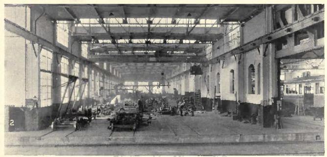
 |
| The Wheel and Axle Department is a busy section. The helical geared ball bearing lathe, Fig. 3, is used almost entirely for turning armature shafts. It is large enough to take the broom shafts of sweeper equipment. The high-speed, 300-ton closed tank type wheel press, Fig. 4, is 54 in. between tee bars and has an 18-in. stroke. A hydraulic cylinder in the bed of the 48-in. wheel boring machine, Fig. 5, lifts wheels into position, and forces the jaws together. Axle straightening is done in the 125-ton hydraulic press, Fig. 6. Push button control for the motors is a feature of the 48-in. wheel lathe, Fig. 7. |
 |
| The Electrical Repair Department is completely equipped for maintenance of all motor and control apparatus. This combination commutator slotting, turning and banding lathe, Fig. 8, is a special machine designed for electric railway shops. Conveniently arranged armature stands facilitate work of rewinding, Fig. 9. The baking and drying ovens, Fig. 10, have thermostatic heat regulation and clock control for turning off the heat. Steel car repairs require Modern Sheet Steel Machines. A hand bending brake shapes sheet steel for splash guards and sand boxes, Fig. 11. The power squaring shears, Fig. 12, cuts side sheets for steel cars and other sheet metal work. |
 |
| The Machine Shop is Most Modern. Surfaces of motor shells, gear cases and truck frames are finished on the planer in the foreground, Fig. 13. A motor shell is being rebored in the horizontal boring mill in the rear. Bushings and pins are made economically on the universal turret lathe, Fig. 14, which feeds bar stock with draw-in collets without stopping the machine. Motor shells and truck frames can be clamped permanently when drilled in the radial drill, Fig. 15. Small surfaces are finished quickly in the 16-in. shaper, Fig. 16. The friction of a disk on the pulley of the grindstone, Fig. 17, rotates a pump to supply water for wet grinding. |
 |
| To maintain and repair cars speedily and keep them up to the modern standards of excellence a completely equipped machine shop was installed. Axle caps are bored with a special jig in the universal milling machine, Fig. 18. The forcing and broaching press, Fig. 19, is convenient for broaching controller handles and pressing in bushings. Truck bolts, turn buckles and special nuts are threaded and tapped in the 2-1/2-in. bolt cutter, Fig. 20. Turning of car axles is done quickly on this lathe, Fig.21. |
 |
| Modern Wood Working Machines eliminate much hand work. Stiles and rails for sash and doors are mortised on this automatic vertical hollow chisel mortiser, Fig. 22. It has a power stroke for the chisel ram. The 36-in. hand, scroll and rip sawing machine, Fig. 23, is a convenient accessory. This four-spindle boring machine, Fig. 24, has a vertical adjustable table. Material is cut quickly into slats and narrow widths on the automatic self-feeding rip saw. Fig. 25. |
 |
| Forge Shop Equipment is suited to light and heavy work. The oil burning furnace, Fig. 26, is used for heating heavy pieces with a long surface. Small work can be done by one man aided by the blacksmith's helper, Fig. 27. Bending, shaping and welding heavy iron can be done quickly with the air hammer. Fig. 28. Rods, angles, and other small pieces are heated in the forge, Fig. 29. Bending and pressing are essential operations of the bulldozer, Fig. 30. It is used also for testing the compression of heavy springs. |
 |
| Electric Trucks are a great convenience for material handling. A crane truck, Fig. 31, handles heavy parts in the material storage yard. Small material is moved quickly by trucks, Fig. 32, with stationary platforms. Controllers, compressors and other car equipment can be placed on work benches by one man with the elevating platform truck, Fig. 33. The Tool Room, one of the shop's show places. Cylindrical, internal and surface grinding are done on the universal cutter and grinder, Fig. 34. The twist drill grinder. Fig. 35, has a special wheel truing attachment. Many operations are done economically on the universal milling machine, Fig. 36. |
Truck Overhauling Systematized in Brooklyn
Electric Railway Journal · Vol. 71, No. 16 · April 21, 1928 · pp 653-657.

At left- Cutting off heads of rivets to loosen parts that require replacement. At right- Truck frames with parts marked in chalk for replacement and rivet heads cut off so as to loosen parts that are to be removed.
In the Coney Island shops of the Brooklyn-Manhattan Transit Lines car trucks are brought in on a dismantling track and go out on assembling tracks. Between and perpendicular to these tracks are eight bays used for inspection and repair work.
By Clarence W. Squier, Associate Editor Electric Railway Journal.
Continuous flow of the work along definite paths is an outstanding feature of the truck overhauling plan carried out in the Coney Island shops of the Brooklyn-Manhattan Transit Lines. The large volume of work handled permits specialization of the various subdivisions to a degree not found in many electric railway shops. Flexibility, so important in this class of work, results directly from the "spot" system used, in which truck frames are placed on stands in definite positions for various jobs, such as stripping, repairing and building up.
Some 20,000 sq.ft. of floor space in the central part of the large main repair shop is devoted to truck overhauling. On the west side of this section the trucks are brought in on one track and dismantled, and on the east side the trucks are assembled and returned to the car bodies on two similar tracks. The space between is divided into eight bays devoted to the detailed inspection and repair of the various parts after they are dismantled. Seven of these have 5-ton overhead traveling cranes controlled from the floor. A 15-ton overhead traveling crane serves the dismantling track and another traveling crane of the same size serves the two assembly tracks.
Trucks are brought into this section of the shop for overhauling every two years. Intermediate and running repairs are made in another section. During the intervening two-year period it frequently happens that trucks are changed, so that when the car comes in for its next overhauling it may have different trucks from those with which it went out originally. In that event the trucks which are under the car when it comes in for repairs are sent to the intermediate truck repair section, and those which were under the car when it went out originally are removed from other cars in the intermediate truck repair section and are sent to the truck overhauling section for the regular scheduled inspection and repair. The procedure insures that trucks are overhauled on their regular schedule and gives increased flexibility to intermediate repair work.
When cars are brought into the repair shop they come in on the track on the west side, which extends into the truck overhauling section. After the car body is lifted off, the trucks are pushed by storage-battery tractors into position on the dismantling track in the truck section. Provision has been made for future installation of control equipment so that trucks can be run under their own power into and out of this section. The proposed equipment consists of contactors and resistors controlled from push-button stations alongside the tracks. A single lead will supply power to the truck to be moved.
Stripping of Trucks is Done Rapidly. As soon as the truck is run in, all large parts are loosened and the 15-ton traveling crane over the incoming track is used to lift off removable parts, such as the motor, gearcase, bolster, elliptic springs, spring plank, radius bar and shoe beams. Motors enter the motor overhauling section immediately adjacent to the track on which the trucks are stripped. The journal boxes, with wheels and axles, are left on the track as the truck frame is lifted and carried to the cleaning room by the crane, after which they are moved to the wheel and axle shop. Waste and oil are removed from the journal boxes and are placed in large drums, which when filled are transported by electric tractors to the waste and oil reclaiming department.
The larger parts removed from the truck, such as bolsters, journal boxes, bottom brake rods, miscellaneous hangers and brake rigging parts, spring planks, radius bars and elliptic springs are placed on large trays with legs to raise them off the floor so that an elevating truck platform can be run underneath for raising and transporting this material to the cleaning room. A clamp is placed over one end of each complete elliptic spring so that the various sections comprising it are held together. Small parts such as bolts, nuts, etc., are put in pails and are carried to the cleaning room by the electric trucks.
The cleaning room at present has three tanks, each 10x14 ft., with its top 3 ft. above the floor level. Two of the tanks have a chemical cleaning solution, steam heated to the desired temperature. The third tank is for rinsing. Truck frames and parts to be cleaned are lowered into the cleaning solution by a 15-ton floor-operated overhead traveling crane which serves the cleaning room. With the present cleaning solution, when the truck and parts come out, after remaining in the tank for three hours, they are about 75 per cent clean. They then are placed over the washing tank and water is sprayed on them with a hose, the nozzle of which has a metal scraper at the end so that accumulations of grease and dirt can be loosened readily.
After this cleaning, the trucks and parts are returned to the section between the incoming and outgoing tracks and are placed on assembling stands which raise the truck frame up to a convenient height for the workmen. The general type of truck overhauling stand used in the B.-M.T. shops was described in ELECTRIC RAILWAY JOURNAL for May 19, 1923, page 853. Those used in the Coney Island shops have locked chests for tools extending across one end. The workman has one key and the foreman a duplicate.
Testing For Defects is Done Thoroughly. In the overhauling bay, truck frames are cleaned with a wire brush. An inspector goes over them carefully to discover cracked parts, loose rivets and worn parts which are to be replaced. He indicates any changes in construction that are to be made. The practice of the company is not only to put the trucks in as good condition as they were when new, hut to incorporate any improvements in material or design that are available. Some of the changes that are now being made during overhauling are the installation of manganese wear plates on journal boxes and pedestals, installation of new end frames, new spring plates and Potter end castings on elliptic springs. The inspector chalks with X marks the parts which are to be taken out and replaced. Parts which in general are being replaced, but which will not be changed on a particular truck are marked O.K. with chalk. For instance, the installation of manganese wear plates has been going on for some time. On some of the trucks that come in the replacement already has been made. The inspector tests the plates with a magnetized iron bar. as manganese steel is non-magnetic, to determine whether the plates are to be replaced or not. He detects cracks in gusset castings which it would be impossible to see without the thorough cleaning to which the trucks are subjected. All defective material is indicated for removal.
After the inspection all rivet heads are burned off with an oxy-acetylene cutting torch if the rivets need replacing or if it is necessary to loosen parts that must be removed. Where cracks in large parts are found, these are burned out to determine their depth and to see if a satisfactory weld can be made. After the heads are cut off, the rivets are driven out with an air punch.
Following removal of defective parts or those which are to be replaced, the new material is installed. New parts are held with rivets if this was called for originally. For this purpose there are several rivet-heating furnaces which can be moved alongside the work for the convenience of workmen. In assembling, all joints are coated with red lead. After the new parts have been attached, the truck is placed over a test jig to make certain that the pedestal jaws line up and have proper clearance. The present practice is to have the jaws 1/16th in. wider apart than the journal boxes.
Individual Parts are Brought Back to Standard Dimensions. All of the material removed from the trucks goes to adjacent benches or departments for dismantling and individual repairs. Brake rigging, for instance, is taken to a bench and completely dismantled. Worn holes are filled in by electric welding and are redrilled. Worn surfaces are also built up and finished to size. This includes such parts as live and dead leaders, motor nose suspensions and shoe-head hangers.
Journal boxes are taken to the blacksmith shop after they come out of the cleaning tank. The old liners for the pedestal ways are removed and the boxes made ready for installation of new ones. From the blacksmith shop they go to the machine shop and are assembled ready for installation in the truck. New torsion springs are installed for the journal box lids. As these require a little more clearance than the springs previously used, a recess has to be cut with the oxy-acetylene torch. The old wear pieces are taken off journal bearings, which then go to the babbitt room, where they are rebabbitted. A new wear piece is then installed and they finally are finished to proper dimensions.
One section of the shop is devoted to inspection and repair of springs. The truck elliptic springs have six sections. After being cleaned with a wire brush, each is inspected carefully for broken leaves. After defective parts have been replaced, the assembled springs are dipped in an oil bath and placed on a rack to drain. Motor nose suspension springs go through the same process.
Assembling is Done on Stands. After everything except the larger parts has been assembled, the truck frames are brought to the truck assembly track and have the journal boxes, wheels and axles placed under them. They then rest on elevated stands while the remaining work is going on. Repair holsters, elliptic springs, spring planks, radius bars, etc., are installed, and motors with gearcases, axle caps, etc., are put in place. The truck frames are sprayed with one coat of black paint before the assembling commences and with another coat after it is completed. The work goes on before the first coat is dry. Dipping tanks and draining racks will be installed later, so that trucks can be dipped in paint at the beginning and end of the assembling instead of paint being sprayed on.
After final adjustments have been made, the trucks are run back to the car repair shop for placing under the car bodies. High-voltage tests and running tests are given the equipment after it is installed in the cars.
The present schedule requires that nine cars be completed each 5-day week, which means that eighteen trucks must be overhauled in the same time, or a maximum of four per day. More than four trucks at a time are being handled, since otherwise one set of workmen might interfere with another. In the overhauling bays are a large number of repair stands on which rest trucks in various stages of repair. The man doing a particular job moves from one truck to the next and completes his work, and then another follows along. This makes the system very flexible and enables the work to be done with surprisingly few workmen. One man is sufficient to do most of the jobs. Of course this could not be done were it not for the ample facilities in labor-saving equipment in the shop.
When the truck comes into the overhauling section, one man dismantles the large parts with the aid of a man in the overhead crane. There is but one man in the cleaning room. The dismantling of brake-rigging parts, such as live and dead levers, motor nose suspensions, and shoehead hangers, is done by one man, who also carries the parts to the benches. There another man dismantles the various parts and does the bench work. The wire-brush cleaning is done by one man, and one inspector locates defects and looks after parts to be replaced. He tests all rivets with a hammer, and marks any blowholes which might be dangerous and require filling up. One man with a blow torch loosens all defective parts, while a machinist with one helper puts on the new ones. A crew of three men do the riveting. One heats the rivets, one operates the air riveter, and the other holds on. Where a rivet hole is too large, or oblong, a welder fills it up and then it is redrilled with an air drill. One man puts on small parts, such as brake-rigging springs. A total of four men do the bench work and inspect various detail parts. On the general assembling track where four trucks are being worked on at the same time, only four men with two helpers are needed.
In the layout of shop equipment and facilities particular attention has been given to prevent unnecessary movement of the workmen in obtaining material for the repairs, in handling it to the job and in the use of any hand tools needed for the work. The material and spare parts for truck repairs are kept on racks and in steel bins and cabinets alongside the work. No order forms or requisitions are used for obtaining parts from these free stores. Most of the parts are of such a nature that there is no temptation toward theft and parts that are of brass or copper are kept in locked cabinets.
Small parts such as bolts, nuts, rivets, etc., are kept in steel cabinets with bins of convenient size. The practice is to replenish material from the general storeroom or from departmental stores at frequent intervals and about one week's supply is kept on hand in the truck overhauling section. This method also provides a convenient check of the material on hand or which may be needed in the immediate future. It also insures that the material is at the spot ready for use as required.
Portable hand and air tools such as riveters, punches, drills, chisels, etc., are issued to workmen on a check system. Each workman has a tool box right at his job to hold his tools, and he can lock it to make sure that the tools are always in place when they are needed. Duplicate keys to all lockers are in charge of the general foreman of the section.
The section is also provided with waste bins and receptacles for parts which are to be moved to other sections of the shop for reclaiming or repairs. All bins and receptacles are of such a form that they can be picked up quickly by an elevating platform truck and moved swiftly and without confusion. The section is also equipped with several inclosed urinals but near the work so no time is lost and workmen have no excuse for leaving the section when work is in progress. All these facilities help to speed up work and insure that highest efficiency is maintained.

Truck overhauling section in Coney Island shops of Brooklyn-Manhattan Transit Lines.

Dropping out wheels and journal boxes while the truck frame is lifted and carried by overhead crane to the cleaning room.

Placing a truck frame cleaning tank.

Dismantling brake rigging at a bench.

Center, left- Washing a truck frame after it has been removed from the chemical cleaning tank. Center, right- Cleaning a frame with a wire brush. At bottom- A truck frame and stand containing journal boxes after they have been removed from the cleaning tank.

At left- Heating rivets in a portable fuel oil forge alongside the work. At right- Riveting new manganese wear plates to truck pedestals.

At top- Jig for testing trueness of pedestal guides on truck frames. At bottom- Placing a truck frame on the testing jig.

At top- Truck assembly section bolsters, springs, motors, shoe beams, etc., are placed on trucks here. At bottom- Pushing an overhauled truck by means of an electric tractor out of the overhauling section for placing under car body.

Dipping tanks and draining racks for springs. The tank at the left contains oil in which the springs are dipped. A quantity of motor suspension springs are shown in piles on the draining basin at the extreme end of the rack are three elliptic springs.

Free stores are located immediately adjacent to the truck overhauling section, parts are kept in bins and larger parts in racks.
Truck Repairs Put on a High-speed Basis
Electric Railway Journal · Vol. 71, No. 18 · May 5, 1928 · pp 729-734.

Installing a pair of wheels in a truck in the intermediate repair section of the Coney Island shops. Repair work is done with the trucks on stands, to raise them to a convenient height for the workmen.
In the intermediate truck repair section of the Brooklyn-Manhattan Transit Lines' Coney Island shops repaired trucks are substituted immediately for those removed so that cars are not withheld from service.
By Clarence W. Squier, Associate Editor Electric Railway Journal.
When repairs to car trucks of the Brooklyn-Manhattan Transit Lines are necessary between regular overhaulings, they are made in the intermediate truck repair section of the Coney Island shops. The methods used are quite different from those common in other railway shops in that trucks are changed from one car body to another. Cars whose trucks require repairs are not withheld from service but are brought into the shop, the defective trucks are removed and replaced by others in good condition, and the cars are then returned to service without delay.
In considering this method it might appear that a large number of spare trucks would be needed. On the contrary, as the work is carried out on the Brooklyn-Manhattan Transit Lines, only six spare trucks have been found necessary, besides those actually required for car bodies, to take care of the truck repairs for the 900 subway motor cars, 50 subway trailer cars and 121 triplex units which are operated on the system. The reason is that trucks from cars which are in the shop for general overhauling and repainting are used to carry out truck repair work. This releases enough trucks so that twenty can be placed in the repair section and worked on at one time.
The facilities and methods used make it possible to carry on the truck repair work continuously and to organize the shop forces along the most effective lines. Returning cars to service quickly or making them available for service without delay is the feature around which the plan for repair work has been built. Any additional cost for spare equipment to carry out the program will be met several times over by the added revenue from the increased service obtained from cars.
The intermediate truck repair section is 480 ft. x 80 ft. This long section has an electric drop pit transfer table, which runs across its center. All trucks enter and leave the repair department by this transfer table, being handled to and from the twenty repair stands on which the work is done by two 15-ton, overhead-traveling, cranes. Ten of the truck repair stands are placed in each of the sections on either side of the transfer table. Along the two sides of the section are numerous cabinets, material racks and bins, workmen's benches, machine tools, rivet heating furnaces and miscellaneous equipment used in the repair work.
Motor leads and brake rigging of trucks which are to be repaired are disconnected in the inspection shop, which adjoins the truck repair section, so that removal is easy. Most of the subway cars of the Brooklyn-Manhattan Transit Lines are operated in groups of three. These are handled as units, being kept together and shopped at the same time. Whenever it is necessary to remove a particular truck the three cars are brought in.
The track over which the cars come in has an electric drop-pit table, supplied by the Whiting Corporation, Harvey, Ill. This is operated in conjunction with two special overhead cranes supplied by the Box Crane & Hoist Corporation, Philadelphia, Pa. The cranes have L-shaped hooks to support the car body while a truck is removed or replaced. When removing a renter truck from an articulated unit it is necessary to support the ends of two car bodies at the same time, so there are two 15-ton overhead cranes with two sets of supporting arms. The crane equipment extends over the truck removal track and is fitted with trolleys and appliances for convenient operation. The cranes are equipped for longitudinal and transverse movements but not for vertical motion as this is taken care of by the drop-pit table. The entire equipment for the overhead cranes and the electric drop-pit table is controlled electrically from a station on the floor alongside the drop pit.
The electric drop-pit table is supported on four upright screws. The lower ends of these screws rest in blocks in a wheeled truck which runs on a track in the pit. Motors for the raising, lowering and transverse movements are mounted on the table, but are controlled from a stand on the floor of the overhauling shop. Locking bars take the live load while the train is moving across the table.
After the train has been placed so that the truck to be removed is in the center of the table, the table is elevated enough to give clearance for easy insertion of the body holding hooks from the crane. The locking levers are then released. There is an electrical interlock so that the table cannot be lowered until the locking bars are entirely unlocked or locked. The table is then lowered to give clearance for removal of the truck, and then, along with the truck, it is moved transversely.
As the transfer table has two surface tracks a truck in good order can be placed on one track before a train is brought in while the truck being removed will be placed on the other track. The transverse movement of the drop-pit table which takes out the defective truck then brings the second truck into position, so that the table can be raised again and the new truck placed in position under the car body. The shop section adjacent to the pit table has three short spur tracks which line up with those on the table in either of its two stationary positions. Trucks can thus be run on and off the table and left on the spur tracks until it is convenient to handle them with the traveling cranes. A truck can be dropped out of a car and a new one installed in a very short time without uncoupling cars.
Control equipment has been ordered for this section so that trucks can be moved to and from the transfer table under their own power. This equipment consists of contactors and resistors controlled from push button stations alongside the tracks. A single lead will supply power to the truck to be moved.
At present the truck repair section has a working force of 20 men during the daytime and 21 men at night and the section repairs an average of from 20 to 25 trucks per day. Running repairs are made only and no general overhauling is attempted. Some of the defects which require removal and repair of trucks are grounded or flashing of motors or armatures, burned off motor leads, grounded brush-holders, worn wheels or those with sharp flanges, worn spring-plank hangers, worn shoe head hangers, broken or worn axle bearings, loose rivets and worn pedestal liners.
A simple but effective record system is used for notifying the shop that repairs are required, for ordering in the cars, for supplying information for a permanent record of truck or motor changes, and for showing the class of work done during each repair period. Two card record systems give immediate information as to the location of any particular truck. One of these is arranged by car numbers and the other by truck numbers. The car cards show the trucks in and out together with dates. The truck cards give the number of cars in which the trucks are installed or removed together with date. The drop table operator records the trucks as they are removed and installed. There are two sets of books so that one may be worked on in the office, while the other is in use at the transfer table. These books are arranged with columns for the number of the truck, the car from which it is removed, the time of removal, the number of the truck which is used for replacement, and the time that it goes under the car.
Attention has been given to labor saving tools so that the men may work efficiently, and so that many of the operations may be performed by a single man, where otherwise several would be needed. Many devices have also been worked out to assist in doing the work quickly and with few men. One example of such equipment is a lever device which is used to compress the coil spring underneath the truck frame and on top of the journal box while a binder bolt is put in position under the journal box. This device, shown in an accompanying illustration, has a block which rests on the truck frame. The short end of the lever has a link with a hooked end which fits into the inside of the wheel rim. A man pushing down on the extreme end of the lever can then compress the spring sufficiently so the binder bolts can be put in position.
Fixtures are used for seating the elliptic springs in position in the spring plank and also in the bolster. To get them in place they must be compressed. Stirrups over the ends of the springs and with a chain connection between the two, the overhead crane lifts and so compresses the springs and they can be forced into place readily.
An accompanying illustration shows a stand that is used for supporting bolsters during drilling. This stand rests on the floor alongside the drill press with the center of the holster resting on the top. The workman can then rotate and move it into a position for drilling.
A crew of three men does the riveting. When not at work on the trucks these men make up spare ends for trucks, transoms, etc., so that these parts are ready to be installed whenever a defective one needs replacement. Packing of journal boxes is speeded up considerably through the use of a pneumatic gun with a packing iron. This method also results in tighter packing and is less tiresome to the workman.
Journal bearings and motor axle bearings are fitted in the truck repair section. Each bearing is fitted to its particular axle, but to speed up repairs bearings are bored out to certain standard sizes that are used most frequently. The diameter of a new motor suspension axle seat is 6 1/2 in. and the minimum diameter to which it is permitted to wear is 6 1/8 in. The bore of bearings will then vary between these extremes. The man responsible for the fitting of bearings tries to keep at least one bearing of each size on hand. These bearings are marked carefully with the exact bore and are stored in locked cabinets at the side of the truck repair section.
As axles come out of trucks, the bearing fits are trued up if they have worn tapered to any appreciable extent. There are thus two general classes for bearings. First, to fit new and worn bearing seats, sizes 6.550 in., 6.540 in. and 6.525 in. are used most frequently, and second, to fit turned and worn bearing seats sizes 6.490 in., 6.468 in. and 6.438 in. are needed most often. In fitting axle bearings the bore is kept between limits of 0.0025 and 0.003 in. per inch diameter larger than the axle seat.
To insure a correct fit, motor axle brasses are clamped in position between the motor frame and the axle cap with the latter bolted tightly. The bore is then gaged carefully, after which the axle caps are taken off, the axle put in position and the bearings and axle caps then installed permanently.
Sometimes it is found that the bore is reduced in size, because of the squeezing, as much as 0.006 in. Axle bearings are of bronze without babbitt lining. The manufacturers furnish them finished to correct dimensions on the outside and rough-bored on the inside.
Axle bearings are bored in the truck repair section with a vertical boring machine, as bearings can be mounted for machining more quickly and conveniently in a vertical position than horizontally. The bearing revolves instead of the boring bar and this results in more accurate machining.
Truck journals have a diameter of 5 in. when new and are not permitted to wear less than 4 3/4 in. Only one size of journal bearing is used. This has a 1/8 in. babbitt lining.
 |  |
| For removal of trucks, cars are brought into the repair section on a single track with a drop-pit transfer table at the center. Two overhead cranes operate in conjunction with the drop-pit transfer table for truck removal. |
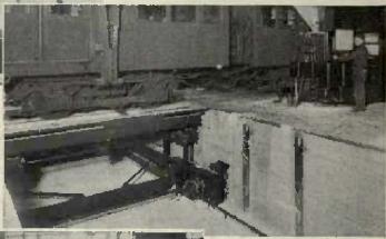 |  |
| The entire operation of dropping out a truck is controlled from a station alongside the drop-pit table. | The transfer table is provided with two tracks so that one truck can be moved into position for installing at the same time that another is removed from the car. |
 |  |
| Overhead traveling cranes handle trucks between the transfer table and the truck repair stand. | Workmen guide the motor so that the motor axle suspension seats properly as the motor is handled by an overhead crane. |
 |  |
| Bolts are installed under journal boxes quickly by means of a lever attachment that compresses the spring between the truck frame and the top of the journal box. | Stirrups fit over the ends of elliptic springs and lifting by the crane compresses them so that they fall into position readily. |
 |  |
| With a truck bolster on a special stand the drilling for filler blocks is done quickly. | The riveting crews make up ends for truck frames and bolsters when not working on the trucks. |
 |
| Journal boxes are packed with a pneumatic gun. This method is less fatiguing to the workmen and gives tighter packing for the waste. |
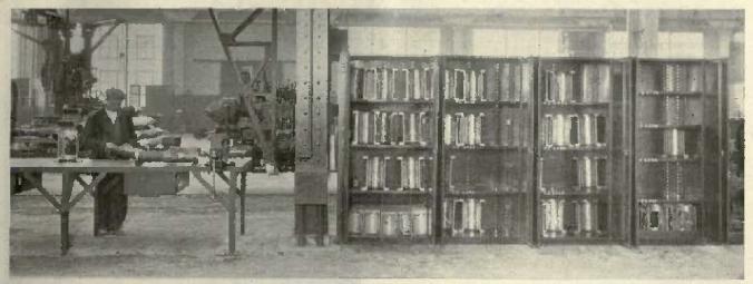 |
| Motor suspension axle bearings are kept in cabinets and are marked with exact dimensions so that they can be fitted readily as needed. Accurate gaging is done on a bench. |
 |
| The two halves of axle bearings are bored out at one operation in a vertical boring mill. |
Wheel, Gear and Axle Maintenance in Brooklyn
Electric Railway Journal · Vol. 71, No. 20 · May 19, 1928 · pp 805-812.

Pneumatic floor lifts provide a convenient means for turning wheels from the incoming and outgoing tracks to that serving the wheel lathe.
For efficient maintenance of these parts on the Brooklyn-Manhattan Transit Lines, the most modern machine tools have been installed in the Coney Island shops. Careful grouping of machines eliminates rehandling.
By Clarence W. Squier, Associate Editor Electric Railway Journal.
Due to the large volume of wheel, gear and axle inspection and repairs on most electric railways, and to the necessity for repeating maintenance operations continually, the work is placed on a production basis more often than other railway maintenance procedures. As a result it is quite common to find wheel and axle work done in sections of the shop set apart for this purpose. The wheel press, boring mill, axle lathe and wheel lathe universally used for this work are usually grouped to eliminate unnecessary handling. With the advantage of a new shop at Coney Island with new machine tools, the mechanical department of the Brooklyn-Manhattan Transit lines has been able to perfect a most effective department for this work.
The wheel and axle department occupies a section of the shop 60x200 ft. Not all of the machine tools for which space is provided have been installed, but when completely equipped the department will include the tools listed in the accompanying table. A large section just east of the shop provides convenient open departmental storage for wheels, axles and shafts. This material is handled by overhead electric crane and electric crane trucks through doorways directly to boring mills or lathes for the machine work. Mounted wheels that come from the truck overhauling or repair departments are handled by overhead crane and enter and leave the section at the wheel lathe end. The entire department is also served by a 7 1/2-ton overhead traveling crane, while groups of machines have jib cranes, there being four of these in the department, each having an 18-ft. boom.
Handling Reduced to a Minimum. The number of times that wheels and axles are handled and the amount of handling equipment has been kept to a minimum by particular attention to location and grouping of machines. Wheel boring is done in the central part of the section. Each of the Sellers 48-in. car wheel boring machines has two built-in jib cranes. While one wheel is being bored another is picked up and held in position by one of the cranes to be swung on to the table of the mill, as soon as the boring of the wheel in the mill is completed. The other jib crane with the previously finished wheel in suspension deposits it on a truck placed alongside.
From the boring mill, wheels to be mounted on axles go to the Chambersburg Engineering Company double-acting, 400-ton, hydraulic wheel press. This machine is used also to press gears on and off. The double pressure heads make it possible to dismount both wheels from a trailer axle without the necessity of removal, after one wheel is pressed off, in order to turn the axle for pressing off the remaining wheel.
Hydrograph chart records are kept of each pressing-on operation. These are numbered consecutively for each day's work, and a notation is also made on each record of the wheel number, the man that fitted the wheel, and the diameter of its bore. Each day's records are put in an envelope and filed by dates. If it is necessary to consult the records for a particular wheel pressing later, the truck overhauling report furnishes the date wheels were changed and number of the wheels. The hydrogram records for that date with wheel number identify the particular operation. In addition, a book record for each pressing is kept at the press. When filled these books are filed.
Subway motor axles have a seat for wheels 7 7/18 in. to to 7 8/18 in. in diameter, and trailer axles have a wheel seat of 6 1/2 in. to 6 3/8 in. in diameter. Pressures for forcing wheels on must be not less than 75 tons nor more than 95 tons for motor axles, and between 70 and 90 tons for trailer axles. The wheel seat for a standard subway axle may vary 0.001 in. plus or minus. Wheels are bored 0.001 in. per inch of diameter smaller than the axle. This gives a pressing-on pressure of from 10 to 12 tons per inch of diameter. Complete information regarding wheel and axle fits for the different equipment in operation, pressing-on pressures, mating of wheels, scrapping diameters, etc., is furnished the wheel and axle department in blueprint form.
In mounting wheels it is the practice to have both wheels on the same axle of the same tape size. A special type of gage is used for gaging wheels. This has one side for gaging new and newly turned wheels and the other for gaging partly worn wheels. New and newly turned wheels are gaged from throat to throat, while worn wheels are gaged from back to back.
As the wheels used on the rapid transit motor axles have diameters ranging from 30 1/4-in. to 34 1/4-in., and gears have outside diameters of 25 in. to 27 in., it is possible to support the wheels at the rim for pressing off. A particular yoke has been supplied by the manufacturer of the press to go over the outside of the gear and fit between the rim of the wheel and the center frame of the press during the pressing. The yoke is suspended from a pipe framework with a roller support so it can be put into position or swung out of the way easily by the operator.
The Brooklyn system was a pioneer in the use of steel wheels for electric railway service, adopting them in 1905. Excellent results and substantial economies have been obtained. By concentrating all wheel and axle work at one point, under the direction of one man, every mile of service consistent with safety is obtained from the wheels.
Checking for Wear Systematized. The different maintenance foremen are expected to see that the wheels are worn to, but not below, the various scrapping dimensions which are furnished them in blue-print form for their guidance. New wheels for subway motor axles are 34 1/2-in. in diameter and can be worn to 30 1/4-in. Subway trailer wheels are of 31 in. diameter when new and can be worn to 27 in. When the wheels removed from the trucks are received in the wheel shop, they are checked carefully with gages to ascertain dimensions and defects. An inspector also checks the axles carefully and measures them to determine whether truing up is needed and also to make certain that the bearing fits on the trued-up axles are above the scrapping limit. If a bearing fit will not true up above scrapping dimensions the inspector paints it red and the wheels and axle are routed to the wheel press for removal of the wheels. The same inspector who inspects bearing fits also determines whether the wheels can be returned to service and indicates any work that is necessary. If it is found that the wheel will not true up to 1/4-in. above the scrapping limit it is marked for removal.
For steel wheel maintenance work the wheel lathe is an important and busy tool. At present, one high-powered lathe is doing the work. This was supplied by William Sellers & Company, Philadelphia, Pa. Three pairs of wheels per hour are turned out, on an average. Handling of the wheels is speeded up considerably through the use of pneumatic floor lifts and a hoist which forms a part of the lathe. The lathe has two turret tool posts, each arranged to hold four tools. There is a roughing tool for the wheel tread, a flange roughing tool, a combined tread and flange finishing tool, and a chamfering tool. The lathe swing is 42 in. and a 3/8-in. cut can be made at high speed. Through the use of an efficient clamping arrangement, wheels can be removed and new ones put in place for turning in two minutes. Only one man and a helper are assigned to the lathe. The helper assists in wheel handling, sweeps up chips, oils the machine, takes wheel measurements and does other work necessary while the wheels are being turned.
The wheels are rolled directly into position in the lathe on a track. Crossing this at right angles are two tracks used for the incoming and outgoing mounted wheels. There are two pneumatic floor lifts, one in the center of each crossover. The helper rolls a mounted pair of wheels along the incoming track to the crossover, steps on a button controlling the valve to admit air to the hoist cylinder of the lift, and the plunger raises the wheels free of the track. The wheels are rotated a quarter turn and then are lowered to the track leading to the lathe. The action is reversed to remove a pair of wheels after turning. This has proved a very easy and quick method for serving the lathe.
Each axle is carefully inspected and tested to detect any minute cracks that would be liable to result in breaking later. The axle, with its wheels in position, is wet with a bath of kerosene while on a test stand. The axle is then wiped dry and is painted with a paint of lime in a solution of one-third alcohol and two-thirds water. The alcohol causes the mixture to dry quickly. After numerous tests, this proportion was found to give a smoother coating than any other combination or composition. A crack retains some of the kerosene. This penetrates the lime coating quickly and leaves a brown discoloration so that detection is easy. Axles without wheels are dipped in kerosene and then wiped dry and painted with the lime. An accompanying illustration shows a crack at the end of an axle that was detected by this method. To get an idea of the depth of the crack the axle was turned down to the different diameters shown. Since this method of inspection was adopted no axles that have undergone this test have broken in service. It has been in use about 1 1/2 years. After testing, axles with wheels mounted are stored on racks to keep them off the floor until they are removed to other departments or shops for mounting in trucks. Wheel racks have four 3x4-in. angles arranged in pairs, each pair spaced wheel gage distance apart. The angles are fastened together by steel straps to form a rigid framework. Alternate pairs of wheels are staggered so as to take up a minimum amount of room. Each bearing seat has a protective covering, made of a number of wooden strips strung on small ropes. Each strip is about 1 in. square and of a length sufficient to cover the bearing surface. By tying the loose ends of the ropes together the covering is held securely.
Bearing seats which are worn tapered, out of round, cut or have rough fillets are turned in a gap lathe. For this work with wheels in position, two heavy duty American 24-in. by 14-ft. geared head engine lathes are used. The bed of the lathe has two gaps for the wheels, the swing in the gaps being 40 in. Each lathe has two carriages, one with two tool posts. With this equipment the two motor suspension axle bearings and one-truck journal bearing can be trued up at the same time.
New axles have bearing seats ^ in. in the rough over size when received from the manufacturers. They are turned and ground to accurate sizes in the wheel and axle department. For this work there are two groups of three machines each. In each group there are two 8-in. LoSwing axle lathes and one 12x96-in. grinding machine. Bearing fits are turned in the lathe to a size 0.015 in. to 0.018 in. larger than standard. They then go to the grinding machine and are finished accurately to exact size. The Low-Swing lathes were furnished by the Seneca Falls Machine Company to be used for axle and armature shaft turning. Their beds are 108 in. long. There are two carriages with three tool posts on each so that six tools can be used for cutting on the same post at one time. As a result of the use of these rapid production lathes the time necessary to finish axles has been reduced to one-fourth of that necessary with ordinary engine lathes.
An accompanying illustration shows one of these lathes turning a large subway car axle. The various finish fits for this type of axle are, journals 5x9 in., dustgu.. surfaces 6 1/8x2 in., wheel fits 7 7/10 x 6 1/2 in., gear seats 7 1/2 x 6 1/8 in., and axle bearings 6 1/2 x 12 3/4 in. The total length of the axle is 7 ft. 1 in. With the improved lathe equipment this size axle is turned ready for grinding in average of three hours. With the single-tool lathe ordinarily used, the machining operations on an axle of this size would require at least three hours for rough finishing and an additional nine hours for finishing cuts. Previously two different lathes were used, one for rough and the other for finishing, so it was necessary to change the axle from one to the other.
In addition to provisions for multiple tools cutting simultaneously, this type of lathe has a geared headstock providing for six spindle speeds and a geared feed with nine changes. The geared headstock is rugged, so as to withstand the severe strain imposed upon it when several tools are taking heavy cuts. The switch for starting and stopping the machine is on the driving pulley shaft and is operated by the shifter rod placed above the table. In order to obtain rigidity the tool holders are clamped directly to the carriage casting itself, which, in turn, bears directly on the bed of the lathe. This eliminates numerous intervening parts in the supports for the cutting tools and avoids possibility of vibration. The cutting tools do not extend across the bed of the lathe, so that the carriage can be run past the tailstock or back rest without moving the tools from their position. A geared pump built into the head of the lathe provides a continuous flow of cutting compound. The volume of axle work in the Coney Island shops permits the lathes to be kept busy continuously.
Finishing of axles by grinding, which is coming into quite extensive use, has been adopted in the Brooklyn shops. Landis 12x96-in. grinders are used. There is a saving of approximately 25 per cent in the time taken to finish axles as compared with that when they are finished in a lathe. There is also greater accuracy of dimensions and smoothness of finish, so that longer life of bearings results. Where wheels or gears are to be pressed on axles, the grinding finish produces more uniform pressure for the pressing and the grinding finish eliminates irregularities common with filing or rolling, so due to the smoother surface there is a better fit and more surface area in contact between the wheel bore and the axle. This method is also of advantage in producing a better fit of bearing so that the pressure per square inch is reduced. As the pressure employed in grinding is not great, there is little danger of particles of emery becoming embedded in the surface of the axle, and all loose particles are washed away with the heavy flush of water used. Axles without wheels that have surfaces to be trued up go to the grinding machine. Those with wheels mounted go to the gap lathes for truing.
The 200-ton hydraulic axle-straightening press forms an important part of the equipment for the axle section. Every axle without wheels that does not go to the grinder goes to this test machine to determine if it is bent. If so, the straightening becomes an added part of the maintenance procedure.
Besides the machine tools, the axle section contains a large number of portable axle racks. Each will hold seven axles with gears mounted and they are placed at convenient locations so that the jib crane which serves one of the various machines can deposit an axle in one of these racks after it is turned and is waiting to go to the grinding machine. After grinding the same jib crane handles the axle to another rack, or an individual axle can be picked up by an overhead traveling crane and taken to another section as desired.
These axle racks are constructed of angles and channels. The ends form a triangle. Two 12-in. channels form the top portions of the ends. To these, 6-in. angles are riveted to form the support for the ends of the axles. To prevent injuries to the axles the faces of these angles are covered with 1/8-in. copper. Gusset plates strengthen the framework at all corners. The complete rack is 5 ft. wide and 8 ft. long. The bottom framework is constructed of 4-in. angles, with a plate at each corner. These are 6 in. wide and 1/2-in. thick and have holes so that tackle can be fastened to lift the entire rack with load by an overhead traveling crane if desired. As the racks are fitted with wheels they can be moved with their load of axles. The wheels are of 8 in. diameter and have a 4-in. face. The front axle is constructed of a 4-in. I-beam and has a center bearing and circular side bearings so that it can swivel for turning sharp corners and moving about.
Maintenance work on wheels and axles for the entire B.M.T. lines is done at the Coney Island shops. There are three other shops where wheels and axles are removed and installed. A wheel supply flat car makes daily trips to and from the shops. Handling of wheels mounted on axles at the Coney Island shops is facilitated by providing a track into the wheel and axle section so the car can be run inside and loading and unloading done with the overhead traveling crane. The top of the wheel supply flat car has wooden blocking bolted permanently in place to keep wheels from rolling while in transit.
The wheel and axle section also does the finishing work on new armature shafts. A Mitts & Merrill external key seater is used for cutting keyways in shafts.
Machine Tools for Wheel and Axle Section of Coney Island Shops.
- Two extra high power wheel turning lathes
- Three 48-in. heavy-duty wheel boring machines
- One 400-ton hydraulic wheel-mounting press
- One 200-ton hydraulic axle-straightening press
- Three 40-in. x 14-ft. heavy-duty geared-head engine lathes
- Four 8-in. LoSwing axle lathes
- Two 12x96-in. grinding machines for axles
- One external key seater
- Two 20-in. wet tool grinders
- One axle-testing stand with tanks

Every axle that does not go to the grinding machine for truing is tested at the 200-ton hydraulic press. If bent, this machine provides a quick means for straightening.

Wheel mounting and check gage. When mounting new or newly turned wheels after one wheel is pressed into position, the stop ^ or S of the mounting gage is placed against the inside of the flange of the wheel pressed in position and the corresponding tread stop C or ) against the tread of the wheel. The second wheel is pressed onto the axle until the opposite tread stop comes in contact with the tread with the corresponding gage point or F in contact with the outside of the flange. For mounting partly worn wheels after one wheel is pressed into position, the stop G or H oi the mounting gage is placed against the side of the flange of the wheel with the corresponding surface I or J resting on the top of the flange. The second wheel is then pressed onto the axle until the opposite stop G or H comes in contact with the inside of the flange of the wheel. In checking wheels when both stops C and D will not rest on the treads of the wheels, they are out of gage.

Layout of machine tools and equipment for the wheel and axle department of the Coney Island shops, Brooklyn-Manhattan Transit Lines.

Boring out a subway wheel. The wheel suspended from the crane on the left is ready to be swung into position. A truck at the right receives wheels after they are bored. The crane at the right handles finished wheels.

A truck load of finished wheels being taken away from the boring mill by an electric crane truck.

A yoke fits between the inside of the wheel and the center frame of the press over the outside of the gear for pressing off wheels from the gear end of the axle.

Pressing a wheel on an axle at the 400-ton hydraulic wheel press.

The yoke used in pressing off wheels at the gear end of the axle and other accessories used in the pressing operation are mounted at the back of the press so as to be swung into position easily by one man.

An average of three pairs of wheels per hour are turned in this wheel lathe.

Rapid Transit Service Requires Careful Checking and Testing of Wheels and Axles. All axles are tested carefully for cracks before being sent out from the wheel and axle department. The axle of the pair of wheels on the stand at the left has just received a bath of kerosene. Axles of mounted wheels on the track at the right have been painted with lime as the second operation of the test. Second view-- Painting the axles of mounted wheels with lime on the test stand.

Third view-- Crack at the end of an axle. The turned sections show the depth and width of the crack at different depths. The bearing fits of axles are protected by wooden strip coverings. These are shown at the right.

Mounted wheels ready for service are placed on racks to keep them on the floor.

Equipment for Axle Work. 1. One of the batteries of three machines used for finishing axles. Two Lo-Swing lathes are shown in the foreground and an axle grinding machine in the rear. Between these are axle racks to receive axles in various stages of completion.

2. Turning an axle in one of the 8-in. lathes with two carriages having multiple tool posts. 3. The finishing operation of axles is done in a grinding machine. 4. Portable axle racks provide a convenient means for storing axles.

5. High-power gap wheel turning lathes are used for turning axle bearing fits with wheels mounted. A supply car is shown at the left as it is being loading with wheels to go to other shops of the system.

An external keyseater for armature shafts forms a part of the equipment of the wheel and axle department.

A convenient departmental storage for wheels and axles speeds up production. Material can be brought in on a car and unloaded by the overhead 7-1/2-ton traveling crane. Wheels are loaded on small trucks and taken to the wheel and axle department by electric crane trucks.
Careful Overhauling of Motors Prevents Service Interruptions
Electric Railway Journal · Vol. 71, No. 24 · June 16, 1928 · pp 972-977.

At left- One of the bays in the motor overhauling section. The machine for installing armatures in box-frame motors is shown in the foreground. At right- Installing an armature in a box frame motor.
With several cars in a rapid transit train a disabled motor may cause delay and inconvenience to hundreds. Motor overhauling in the Coney Island shops of the Brooklyn-Manhattan Transit Lines is planned to prevent failures on the road. The most modern practices are used.
By Clarence W. Squier, Associate Editor Electric Railway Journal.
Highly systematized methods are used throughout the motor overhauling department in the Coney Island shops of the Brooklyn-Manhattan Transit Lines. This work is done in two bays each 20 ft. wide by 100 ft. long. Over each bay is a 5-ton overhead traveling crane controlled from the floor. Motors are lifted off trucks at one end of the section when the trucks go through the shops for general overhauling. The department also does intermediate repairs to motors when it is necessary to remove them from trucks. This section is adjacent to the truck overhauling department so that handling is kept to a minimum.
All motors are of a box-frame type. This is of particular value in standardizing the work. The first thing done when a motor is received in this department is to pull waste from axle caps and armature bearing housings and drain off the oil. The oil and waste are placed in steel drums and go to the oil and waste reclaiming department. Next, for removal of armatures, the motors are placed in a dismantling and assembling machine, of which there are two in the section. One is used for taking out armatures and the other, at the opposite end of the section, is used for assembling.
The machines are of a type quite generally used by electric railways for the purpose. The base has two 9-in. channels 12 ft. 3 in. long. These serve as tracks for the carriage which supports the motor shell. End uprights of 1/2x4-in. steel support a headstock and a tailstock with spindles with coned ends to fit in the centers of the armature shaft. The carriage has a spindle with collars at one side over which the motor axle bearing suspension fits. At the other side the carriage has a supporting framework with a plate to support the nose of the motor. The motor is thus supported on the carriage, the same as it ordinarily is on the car truck. Accompanying illustrations show the construction.
To remove an armature the motor is placed on the carriage, the shaft is centered in the head and tailstocks and locked in position. The pinion end housing is then unbolted and the motor shell as it rests on the carriage is pushed in the direction of the commutator end of the frame. The long spindle passes through the motor shell. The commutator end housing remains with the motor shell, but the pinion-end housing stays on the armature shaft until the pinion is removed. When the motor shell has cleared the armature, the latter is lifted out by the overhead traveling crane and is placed on an armature truck. In handling, a sling with a broad supporting surface is passed around the armature at its center. Pinions are removed by means of a pinion puller, end housings are removed and the armature is sent to the department of electrical repairs for cleaning, testing and repairing if necessary. Several armature trucks are towed together by one of a large fleet of storage battery trucks.
Two general types of armature trucks are used. One is of sheet steel construction with three wheels: The center framework forms a cradle to carry the armature. The second has an angle-iron framework with cast steel ends hollowed out to receive the armature shaft ends. There are four wheels, an 8-in. one on either side at the center and one^4-in. wheel in the center at each end. This latter truck is particularly convenient for handling armatures into and out of the baking ovens.
An armature suction blower is to be installed in the motor overhauling section for cleaning. When this is ready armatures will be cleaned before they are sent to the department of electrical repairs.
The end housings are taken to a motor-driven hydraulic press where the armature bearings are pressed out. Housings and axle caps are then placed in a chemical cleaning tank where they remain for about 1 1/2 hours. There are two tanks each 4 ft. x 6 ft. x 3 ft.6 in. high. One has the chemical cleaning solution and the other has water for rinsing. After cleaning, the housings and axle caps are wiped, inspected and gaged for wear, defects or needed repairs. If they pass the test they are then ready for re-use. All bearings are sent to the babbitting department.
Motor frames are overhauled on work stands. Brushholders are removed and sent to the department of electrical repairs for general overhauling and adjusting. All connections to and between field coils are broken and a careful inspection is made for loose joints. Fields are tested from the 600-volt shop circuit. Any that show signs of short circuits or grounds are removed and sent to the department of electrical repairs. Field coils passing this inspection are not removed from the motor frames. After repair, connections are made again and the entire inside of the frame and the field coils is given a coat of insulating varnish.
Some of the motor frame overhauling is done on stands to raise the parts to a convenient height for the workmen. The stands are 5x8 ft. with a structural steel framework. Each has space for two motors. Special overhauling stands, shown in one of the illustrations arranged so the motor can be turned to any position desired, are used for most of the overhauling. Two circular end plates are bolted to the motor frame by means of the bolt holes used for fastening the armature housings in position. The end plates rest on bottom supports with rollers, so that the motor frame can be rotated readily. The base is 3 ft. 10 3/4 in. long by 3 ft. 4 in. wide and the center of the motor frame is 3 ft. 7 in. above the base, which rests on the floor.
In general the motors now in use on the B.M.T. subway cars have not been in service long enough to have excessively worn axle-cap or armature-housing fits. However, these are all gaged carefully to make certain that there is no excessive wear. In some motors a slight warping has occurred in the motor suspension projectors to which the axle caps fit. When this is enough to cause improper alignment or fit of the axle bearing, low spots are built by welding, the fit for the axle caps is planed off and the frames are rebored. This work is done in the machine shop section.
An accompanying illustration shows a motor frame set up in a planer for machining off the axle cap fit. Another shows a motor frame in the double spindle boring mill having the axle bearing fits bored out. The large 48-in. planer was furnished by the C. A. Gray Company, Cincinnati, Ohio. It has a 12-ft. table and three heads for holding tools, two on the cross rail and the other on the side of the column for facing and side cutting. All heads have automatic feed in either a horizontal or a vertical direction and they can be turned to any angle required by the work. The cross rail and all heads are raised and lowered mechanically. All bearing surfaces have forced-feed lubrication.
The double-spindle horizontal boring mill, furnished by the Giddings & Lewis Machine Tool Company, Fond du Lac, Wis., has special attachments for boring at one time both the axle-cap and the armature-housing fits for the subway type motors. All adjustments are made mechanically. The machine can be used as a single spindle boring mill by removing the extra plate from the table, which carries two boring bars, and by taking of the double spindle boring attachment at the driving end.
The practice of the B.M.T. Lines is to bore armature bearings after they are pressed into housings. The bearings have a thin babbitt lining with cast-in oil grooves. This eliminates handling of the large end housings to cut oil grooves after the bearings are bored. Each bearing is fitted to the armature shaft with which it is to be used. Bearings are pressed into housings with a motor-operated hydraulic press. A gage shows the pressure as each bearing is pressed in. An average pressure of 5 tons is used.
Illustrations show the jig used to insure accurate boring of the bearings after they are pressed into housings. This will take both the pinion end and commutator end housings for three different types of motors, Westinghouse types 300 and 50-L and General Electric type GE-248. The jig really consists of two fixtures, an inner and an outer one, the inner one being used for 50-L housings and the outer one for types 248 and 300 housings. Both fixtures are centered accurately on the face plate of the boring mill by slots and keys. The inside fits into which the housings go were bored out on the machine with which they are used. They are 1/32-in. larger in diameter than the housings.
The inside fixture has three locking arms and three indexed set screws. The locking arms center the housing to be bored and the set screws are then tightened until the index on each is the same. This insures accurate centering of the housing with respect to its fit in the motor shell.
The outside fixture has four gage rings, one for use with each of the four different types of housings that are bored in the jig. The gage rings are centered accurately and locked in position by a set of indexed screws which move centering pins into position by the action of beveled surfaces. When a ring is centered accurately all the indices are the same.
Great care is used in the removal and installation of pinions. Pinions are heated in a hot-water tank so that the bores are expanded previous to installation. All teeth are gaged for wear. A discard gage used to determine the scrapping limit is illustrated. When the top projection touches the end of a tooth, the limit of wear has been reached.
A feature of the motor overhauling section is the provision made for storing parts used in overhauling adjacent to the work. Motor leads are cut to exact dimensions and stored in racks. Locked cabinets contain brush-holders, bearings, connectors and other brass or copper parts. Storage racks are used for housings and axle caps and locked boxes hold the overhauling tools.

Removing a pinion from the hot water tank for installation on armature shaft.

Limit of wear gage for gears and pinions.

Floor plan of the section in the Coney Island shops devoted to motor overhauling.

Details of machine used for removal and installation of armatures in box frame motors.

An armature suction blower is to be installed in the motor overhauling section for cleaning. When this is ready armatures will be cleaned before they are sent to the department of electrical repairs.

Type of armature truck used for running armatures into baking ovens.

Chemical cleaning and rinsing tanks. Housings and axle caps are cleaned here.

Details of rotating motor shell work stand.

Working on a motor shell after installation in the rotating work stand.

Tightening lead cleat with motor shell on one of the stationary work stands.

The line drawing on the left shows assembly of the jig used for boring motor bearings after they have been pressed into housing. The center drawing shows the inner fixture of the jig used for boring armature bearings. In the drawing on the right are shown the details of gage rings used with the outside fixture for boring armature bearings after they have been pressed into housing.

No. 1. Machining a motor axle suspension bearing fit in the large planer.

No. 3. Pressing an armature bearing into a motor housing by means of the hydraulic press.

No. 2. Boring out an axle bearing fit in the double spindle horizontal boring machine.

Boring out an armature bearing after it has been pressed into housing. A special jig is used for centering the housing accurately.
Special Inspection Increases Shop Efficiency
Electric Railway Journal · Vol. 73, No. 7 · February 16, 1929 · pp 273-277.

No. 1. Workmen cleaning equipment by use of compressed air. No. 2. Inspector at work on switch group. The receptacle for drop light and the cut-out switch can also be seen at the left.
By concentrating the work of inspecting subway cars at the Coney Island Shops, the Brooklyn-Manhattan Transit Corporation has built up a force of specialists who perform their duties with unusual skill and speed.
By Clarence W. Squier, Associate Editor Electric Railway Journal.
Preventing delays and equipment troubles in service is the real function of the inspection shops of the Brooklyn - Manhattan Transit Corporation. If a car gives trouble on the road the first question is: "When was that car inspected last?" and next: "What work was done and who did it?" This information is made available through a simple but accurate record system that starts delivered at the shop for inspection department and continues through the repair work. Car numbers are entered in a book by the inspection clerk as the cars are received. The clerk then hangs four inspection cards on each car. There is a blue card for carbody work, a buff card for truck inspection, a green card for electrical equipment and a pink card for pneumatic equipment. Each card has a list, arranged alphabetically, of the equipment to be inspected, lubricated or tested. At the top of each card is space for the car number, the date and the name of the shop. The body of the cards has three columns. Items are listed in the first column. The second provides space for the signatures of inspectors, and the third is for the names of the assistant foremen who checked the work. At the bottom is a line for the signature of the foreman inspector.

No. 3. Car body inspectors at work repairing windows and hand straps.

No. 4. Packing of journal boxes is removed and new oil soaked waste used to repack on 180-day inspection basis.
The work of inspection is divided into four major classifications corresponding to by the transportation those given on the inspection cards. A foreman supervise the various stages of the work for each classification. There is also a general foreman and an assistant general foreman, a superintendent being at the head of the entire shop organization. Inspectors take care of the inspection of that particular class of car equipment to which they are assigned. The work under each of the major classifications is further specialized so that in electrical equipment, for example, items are subdivided into eight groups, each of which has an inspector and assistants who devote their attention to that particular work. Pneumatic equipment is likewise divided into six groups, with special inspectors for each classification. The inspector certifies, by signing the card, that he has inspected the particular class of equipment opposite his signature and put it in good condition. As a final check on the work the foreman of each major classification signs each card for his class of work to indicate that he has examined the car and believes it to be in fit condition for operation.

No. 5. To lubricate center and side bearings, cars are raised by pneumatic jacks. No. 6. Dressing up trucks and connecting their brake rigging after receipt of cars from the intermediate truck overhauling shop.
The cards are made part of the official shop record and provide an easy and accurate source of information as to who inspected an individual item of equipment and the date when the inspection was made. The individual signatures on the card leave no possibility of question as to who is responsible. After the cards leave the custody of the foreman and before they are filed each is checked by the office staff to make sure that there is individual certification as to the inspection and checking of each item of equipment and also the general certification by the foreman on each card.

Four different cards are filled out for each car being inspected at the Coney Island Shops. These include cards for car body, trucks, electrical equipment and pneumatic equipment.
An idea of the degree to which specialization is carried and the manner in which the electrical equipment is subdivided may be obtained from a brief outline of the work. One man inspects and tests the batteries. A second inspects and lubricates the electric brakes and the plug switches, "Power On" recorder, relay and toggle switch. A third man takes care of the inspection of the buzzers, switches, door-operating boxes and incidental magnets, interlocks, signals, cutouts and plug contacts. A fourth devotes his attention to the inspection of contact shoes, and beams with the incidental fuses, shunts, fuse boxes, springs and leads. A fifth inspector specializes in coupler equipment such as slides, fingers and shunts together with the cable hangers and clamps, junction boxes, jumpers, receptacles and covers. A sixth man is detailed to inspect electric trip switches, cable couplers, the motors with their leads, brushes, brush-holders and connectors. The lubrication of the automatic stop device, hangers and bolts and the trip switches, together with the testing of main control circuits and electric trip circuits is taken care of by this inspector. The compressor switch, main switch, resistance and leads, line switch with its fuse, resistance, overload trip and operating relay, together with the interlocks, magnets, switches and drums of the switch group are inspected by a seventh man, who also lubricates the overload trip, the line breakers, the potential and accelerating relays, control cylinders and control contacts. An eighth man inspects charging relays, fans, heaters, indicators, key switches, lights, markers, destination signs, master controllers with incidental reset switches, advance switches, EMF and other relays for control contacts, doors, emergency lights and resistances, in addition to which he tests door-control circuits.
Specialization of work and the efficiency of its performance have been assisted by having a new up-to-date shop. The inspection shop is a separate building located at the west side of the Coney Island shop group. It is 86 ft. wide and 600 ft. long. Vacant space to the west of the present building is to be used for additions as the volume of work increases. Four tracks pass entirely through the building from end to end. These are provided with motor-operated curtain-type doors so cars can enter and leave from either end of the shop.

Electrical inspectors at work on panelboard and door operating contacts.

No. 2. The battery bench has a shelf underneath for storage of batteries. No. 3. Shoe beam racks along the wall of the shop.
Each track has a pit for its entire length. Tops of track rails are 15 in., above the floor level. The rails are supported on cast-steel chairs so there is a clear space of 9 in. between the floor and the bottom of the rail. Pits have a depth of 3 ft., 9 in. below the tops of the rails and are 4 ft. wide. The pit walls and floor are of concrete, and the floor is sloped to a drain at the sides. Special attention was given to the lighting arrangement for the pits. Lamps are spaced 14 ft. apart and are staggered in relation to those on the opposite side of the pit. White enameled porcelain reflectors in the wall niches, with lamps projecting at an angle, throw the light upward to illuminate the undersides of cars. Receptacles are provided for plugging in drop lights. With each receptacle there is an inclosed switch so connected that with the drop-light plug in position, operation of the switch connects the drop light in the circuit and cuts out the adjacent pit light.
Receptacles are provided also for inserting plugs to furnish current for testing various pieces of electrical equipment on the cars. Where the apparatus to be tested is inside the cars it has been found most convenient to use a pole test circuit which hooks over the overhead trolley. There are no third rails inside the shop, and as the subway cars are provided with contact shoes but not with trolleys a special overhead traveling trolley with cable connection is used to supply power for moving the cars. The construction and operation of this overhead traveling trolley was described in ELECTRIC RAILWAY JOURNAL, March 18, 1922, page 474.

No. 4. Work benches and maintenance material rack. No. 5. Carpenter and glazier's work bench. Racks for glass are seen in the background.
A compressed air pipe runs alongside each pit, with cut-in valves approximately every 20 ft., for use by the inspection force when testing the pneumatic equipment on cars and for cleaning purposes. Pits are provided with steps at each end and, at frequent intervals along the side, there are toehold niches to enable workmen to get in and out without having to go to either end. Cross planks with metal angles at the end to keep them firmly in place are also provided at frequent intervals, so that it is unnecessary for shop employees to jump pits when going from one side of the building to the other. Short stepladders are kept in the pits, so that there is no excuse for men standing on boxes or other makeshift equipment when their work requires them to get up close to the floors of the cars. Subway cars, with the exception of service cars, electric locomotives, etc., have their regular inspection on a 1,500-mile basis. A leeway of 150 miles either way from the standard is allowed. This makes it possible to place the same number of cars over inspection pits each day. Where any subway car has not made the specified mileage in a period of 30 days it is arbitrarily ordered into the shop for inspection.
Inspection work is done at the Coney Island shop on 537 subway motor cars, 12 trailers and 116 triplex units. In ordinary service the cars operate the 1,500 miles in about a week's time. At present inspection work is done by both day and night forces, each working 50 hours per week. About 60 per cent of the cars are inspected by the night forces and 40 per cent by the day forces.

No. 1. General view inside inspection shop. At the right is seen the arrangement of racks and benches for material.
In addition to this regular mileage inspection, certain special heavy inspection work is done on a 180-day basis. Six cars are given this heavy inspection by the day forces each day. This 180-day heavy inspection is a convenient way of taking care of work that would interfere with the regular schedule if included in the ordinary inspection. Moreover, by working on only six cars a day, the men have more time to do the work carefully and efficiently than if done on regular inspection.
With this systematic arrangement of work and with the various inspectors classified so that they have a definite portion to do, it is possible to plan the work so that it is done most efficiently. To prevent interference between groups whose work is located in the same part of the car or of groups whose work might interfere because of a common location on certain definite parts of equipment to be inspected, two groups usually start working from opposite ends of the pit so that they cross each other's path only once.
In the regular work of inspecting trucks, inspectors examine the brake rigging, axles, wheels and brakeshoes. If there are any adjustments of brake equipment required that make it necessary to send the trucks to the intermediate repair shop, the inspector notes this on a prescribed form and arranges to have the truck transferred to the other shop. So as not to withhold the car from operation, the regular procedure is to substitute a serviceable truck for the bad order one. The inspection force then prepares the bad-order truck for delivery to the intermediate repair shop and also makes all connections on the good truck that has been substituted.

At left- Water rheostat and switchboard used in the testing and adjusting of line switches. At right- In the foreground are cabinets for workmen's tools. Back of this are racks used for distilled water and behind these is the foremen's pulpit office used by the electrical foreman.
Other inspection work on trucks includes the lubrication of all wearing or movable parts. The waste in journal boxes is inspected and a packing iron is used to make certain that the waste is properly placed under the journal seat. Oil in armature and motor axle bearings is measured by gage provided for this purpose, and additional quantities, as indicated by the gage, are supplied. The packing used in the motor axle bearings and journal bearings is removed and re-treated on the 180-day inspection period. A two-man crew also lubricates both side and center bearings at the 180-day inspection. Car bodies are raised by pneumatic jacks placed on both sides. Shoe beams also are given a heavy inspection on an 180-day basis. This includes cleaning and scraping off the dust which has accumulated. After the cleaning the beams are repainted with an insulating paint.
To inspect the motors the covers are removed, the carbon brushes examined for wear and the commutator brush-holder and field leads looked over. Polepiece clearance for the armature is checked also. Surrounding parts of the armature and brush-holder are examined to discover any accumulation of dust, and compressed air -is used to clean where necessary. After having been blown out with compressed air, porcelain insulators of brush-holders and the V rings at the ends of commutators are wiped off carefully. Motor leads and motor lead connectors are examined closely on regular inspection. Attention is also given to shoe fuses, terminals, fuse boxes, contact shoe leads, jumpers, etc., and repairs and renewals are made where necessary. Contact shoes are gaged and adjusted to proper height.

Light from the pit lamp is reflected upward.

Pit and rail construction.
The control equipment, including the master controller, line switches, reversers, unit switch groups and operating interlocks are inspected carefully. Contacts are replaced where necessary, and any accumulation of dust is removed by blowing out with compressed air. After cleaning, the parts are lubricated. Operating magnet valves are tried out individually and also in their regular operation from the master switch. Motor resistors are inspected as part of the control inspectors' duties. Where it is found necessary to replace any parts, these are changed by a separate repair crew so as not to interfere with the regular inspectors' work. Switchboard contacts are cleaned and insulating paint is applied on the 180-day basis.
Electric parts of the automatic air and electric couplers used on the subway cars are overhauled on the 180-day basis. The slide contact pads are removed and contact fingers are replaced where excessively worn. The interior housing is cleaned out thoroughly. The tension on contact fingers is tried and fingers are gaged for proper height. The contact pad is inspected for wear on the contact surface. Where necessary, new pads or other parts are replaced at this time. On regular inspection where the electric portion is not dismantled the slide pad is pressed in so as to make an inspection of the contact fingers, and whenever an unusual condition is observed the housing is taken apart and required adjustments made. The drawbar automatic locking devices and equipment are tried out on regular inspection.
Men assigned to the work of inspecting couplers also inspect train line cables, jumpers and receptacles as well as the hangers from which they are suspended. This work is done on the 1,500-mile inspection basis. Electric automatic stop trips with which subway cars are equipped are tested on every inspection. Covers are removed, the electric contacts and fingers are inspected, the interior wiped and parts lubricated lightly. Tips are then reassembled and gaged for proper adjustment above the running rail and the proper centering of the trip arm after it is applied. The action of the electro-pneumatic valve used in the circuit is tested. Where adjustments or renewals are required on the trip equipment these are done by the inspector who examines them.
The main panelboard, which includes the light, heat, fan, battery and compressor switches and also the various fuses used in connection with these switches, is examined on every mileage inspection, as are also the control and door-operating circuits.
Car cleaning is taken care of by the inspection shop. This includes the sweeping out of cars every 24 hours and the wiping off of interior portions. This work is all done at night or early in the morning before the cars go into morning rush service. Cleaning of glass is done at the time the cars come in for regular inspection on the mileage basis. This cleaning also includes the cleaning of globes and interior fittings. A combination of sand and pumice is used in damp form to cut the grease which collects on the window and door glass.
Sources
Electric Railway Journal, McGraw Hill Company, Digitized by Microsoft, Americana Collection, archive.org. BMT Monthly.